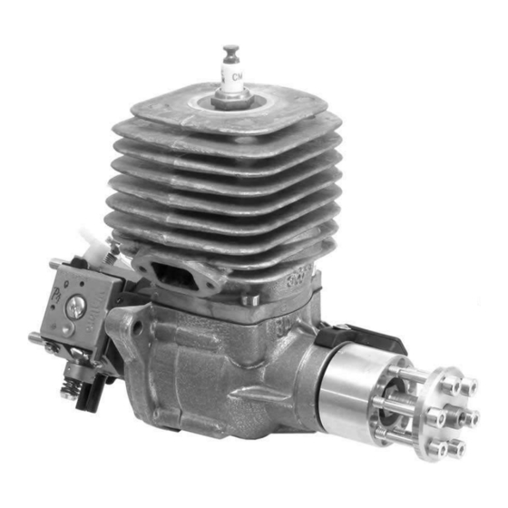
3W 24i 사용자 설명서 - 페이지 5
{카테고리_이름} 3W 24i에 대한 사용자 설명서을 온라인으로 검색하거나 PDF를 다운로드하세요. 3W 24i 18 페이지.

Mount the engine to the motor box with high tensile bolts. Once mounted you now have a sub-
assembly that you can mount to your fuselage. Spacers can be made from hardwood dowels (3/4"
to 1") or machined aluminum bar stock to adjust your down and side thrust. These spacers should
go between the motor box and fuselage and not the motor box and engine.
It is strictly prohibited:
To mount the engine directly onto spacers for the following reasons:
a. If the spacers are too long and/or not stiff enough the engine could vibrate leading
to the crankshaft starting to twist, further leading to the crank case being destroyed.
b. If spacers are used to adjust the side and/or down thrust and this spacing no longer
provides an even plane (i.e., a flat and level surface) the crank case will be distorted,
leading to the crankshaft starting to twist, further leading to the crank case being
destroyed.
To mount the engine directly onto a large (wide) former or firewall for the following reason:
a. If the cylinder(s) is/are too close to this wide former or firewall, the floating air cannot
pass freely over and then away from the cylinder(s). Cavitating hot air can/will overheat
the engine.
Engine Cooling
A proper cooling system is vital for any engine. An air cooled engine requires an appropriately
sized air intake. Also to keep this air cooling process working the incoming air must be exhausted.
Further, the exhaust air outlet should be four times (4X) the size of the cool air intake.
Example:
•
10 square inches of air intake area would require
•
40 square inches of exhaust air outlet area
It is up to you to insure that the air flows freely to, over, and away from, the hot cylinder(s) and
muffler(s). Please refer to Engine Installation for motor box considerations, and to the following
24i / 28i Engine Manual
tips on baffling.
more infos: www.3w-modellmotoren.de
