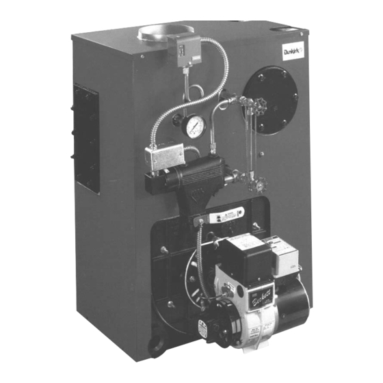
Dunkirk Empire 3ES1.00 설치 및 운영 매뉴얼 - 페이지 10
{카테고리_이름} Dunkirk Empire 3ES1.00에 대한 설치 및 운영 매뉴얼을 온라인으로 검색하거나 PDF를 다운로드하세요. Dunkirk Empire 3ES1.00 20 페이지. Oil-dired cast iron steam boilers

Chimneyand ChimneyConnection
CHECKYOURCHIMNEY
Followlocalcodes.In the absence of localcodes,followANSI/NFPA 31
Installation o f OilBurning Equipment, latestedition.
This is a very important p artof yourheatingsystem.Noboiler,however
efficient i ts design, c anperform satisfactorily if thechimney thatservesit is
inadequate. Checkyourchimney to makecertain that it isthe rightsize,
properly constructed and in soundcondition.
It is cheaperto rebuilda poorchimney thanto payexcessive fuelbills.If
yoursis an old masonrychimney, a newsteellineror a new
prefabricated c himneymaybe thebestsolution. T hefollowing chartshows
recommended m inimum chimney sizesbasedon Table3 and Figure6 of
the I:B:R Testing and RatingStandardfor HeatingBoilers,Sixth
Edition, J une1989.
MUST
BE REQUIRED
MIN*
IMUM
HEIGHT,
MUST
BE
AT LEAST
3 FT.
HIGHER
THAN
HIGHEST
PART
OF
PASSAGE
THROUGH
ROOF.
MUST
BE AT
LEAST
2 FT. HIGHER
THAN
ANY
NEIGHBORING
OBJECT.
MUST
HAVE
AN
UNOBSTRUCTED
TOP
OPENING,
MUST BE AT LEAST
4 INCHES THICK -
AND BE LINED.
_l_
CHFM_ I
.60- i 30
1 5
13Iol
80
15
i,81o2,00
20
FIECOMMENDED MtNiMUM _IMNEY
SIZES
=!:
_ER_
LNER;
_!NNqY'
i_DE
I_
8"×8 '
6'
6:5_x 6_'
8' x 8"
7'
, 6_f;_" × 6_!4"
[:<]r e #_@:(Y)8 8_ee 2,#_ if,,8J3_es_ _i,
ad_ 3 feetIo cblm_qeY h e_gP4_
[_!et la Fiqure 1@t
Foradditional chimneydesignandsizinginformation, consult t heASHRAE
1996HVACSystems and Applications Hand-book, Chapter30,Chimney,
GasVentand Fireplace Systems; o r theNational S tandard for Chimneys,
Fireplaces, V entsand SolidFuelBurningAppliances, ANSI/NFPA 211.
CHIMNEY CONNECTOR ANDDRAFTREGULATOR
Your boiler requires7" diameterchimneyconnectorpipe on 3 section,8"
diameterchimneyconnectorpipe on 4 section.You mustalso use a dralt
regulatorpackedwith boiler.Properlyinstalled,the regulator w ill controlthe
draftautomatically. It is better to installit in a horizontal sectionofthe pipe;but
it maybe in an angledor vertical s ection. J ustmakecertain thatthe"top"is at
top- andthattheshortpipesection whichholdsthe Vaneis horizontal. Install
it ascloseaspracticable t o theboiler.
To install t hechimney connector, s tartatthe boilerandpreferably t akeoff
fromthefluecollector c ollarwithan elbow- theninstallthedraftregulator
next,makingit horizontal. Whentheregulator i s in place,startatthe chimney
andwork backto theregulator. J ointhetwo sections with a Drawband. T he
horizontal pipemustslopeup toward the chimney at least1/4inchperfoot.It
mustnotleakandmustbe firmlysupported. Joinsections withat leasttwo
sheet-metal screws.Supporteverysecondsectionwitha stovepipe wire.
MINIMUMVENTPIPECLEARANCE
ALTERNATE
POSITIONS
TOP
1
MUSTSLOPEUP
AT LEAST
1/
PER
FOOT
OF
HORIZONTALRUN
DRAWBAND
LAST
PIECE
INSTALLED
I
I
L
_,TIGHT.
SMOOTH,
CORRECTLY
SIZED.
I
I
t
I
&LEDIN
THIMBLE
TIGHT
DOOR
DRAFT
REGULATOR
VANE
Woodandothercombustible materials mustnotbe closerthan18"fromany
BALANCED WEIGHT
surfaceofthevent pipe.
