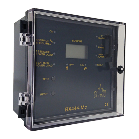
Duomo BX444-Mc 매뉴얼 - 페이지 10
{카테고리_이름} Duomo BX444-Mc에 대한 매뉴얼을 온라인으로 검색하거나 PDF를 다운로드하세요. Duomo BX444-Mc 12 페이지.
Duomo BX444-Mc에 대해서도 마찬가지입니다: 설치 및 사용자 설명서 (9 페이지)

In case of alarm
Extinguish any naked flames.
Do not switch lights or electrical devices on or off.
Open all windows and door to increase ventalation.
•
If the ALARM LED is off the levels of gas have dropped. A responsible, qualified person is now safe to find the cause of the alarm.
•
If the alarm sound reamins constant and the cause is not evident or not possible to eliminate turn off the emergency isolation valaves to the area and
contact your gas provider emergency line. They will advise accordingly.
Troubleshooting
The Problem
No light are illuminated on the fascia of the
detector
One or all of the sensor fault lights are
illuminated
Sensor fault continues to alarm
The detector is subject to repeated alarms
The detector is in main alarm condition and
the main gas valve is not closing
There is no supply to the solenoid valve
The sensor is connected but no LED is lit on
the front fascia
Still experiencing difficulties?
If you have made the checks above and are still experiencing diffculties then please call Duomo (UK) Ltd on
+441905 797989
for technical assistance.
t: 01905 797989
e: [email protected] | w: www.duomo.co.uk
Check that the electrical supply is reaching the device and that the plug in terminal rail is pushed
into place.
Check that the plug is inserted correctly.
Check that the sensor wiring is correctly terminated at both the detector and the sensor. Check that
12V DC is present at the sensor. The green LED on the sensor should be illuminated.
By pressing the TEST button on the detector fascia it is possible to check the efficiency of the
device and if the sensors have been connected correctly.
Check the sensor wiring. If the red Overload LED is illuminated then a short circuit or overload has
occured on the sensor or connecting cable.
Ensure that there is not an occasional gas leak. This may be due to a valve or joint which leaks
under pressure.
Check that the connections are correct and that power is supplied to the valve i.e. The valve is not
stuck in the open position. The function of the alarm relays both the Pre-Alarm and the Main Alarm
can be checked by pressing the TEST button on the detector fascia. Check that the main alarm
action is configured for a latching alarm.
(Switch 2 on 5th DIP switch - See Configuring the BX444Mc)
The Main Alarm relay is a volt free contact, therfore you must connect the live supply to the
common of the main alarm relay contacts terminal 10.
A supply will then come from terminal 12 to the solenoid valve.
Check that the DIP switch is set to the ON position for the sensor
(Switch 1 on one of the first three DIP switches - See Configuring the BX444Mc
10
The Solution
