FreeBytes RadioKit-120 조립 및 작동 매뉴얼 - 페이지 3
{카테고리_이름} FreeBytes RadioKit-120에 대한 조립 및 작동 매뉴얼을 온라인으로 검색하거나 PDF를 다운로드하세요. FreeBytes RadioKit-120 11 페이지. 20μ cw ham radio transceiver kit

mixer during reception.
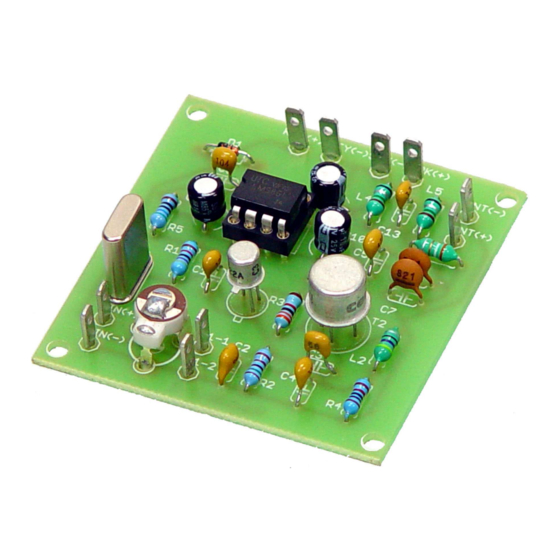
AMPLIFIER/MIXER
During transmission the RF power delivered by the oscillator is amplified by T2
and delivered to the antenna through a band pass filter. During receive the
signal received by the antenna is applied at the collector of T2 through the
same band pass filter. This signal is mixed with the oscillator signal applied to
the base of the same transistor and the audible difference/sum between the
two signals is taken from the emitter and applied to the input of the audio
amplifier chip IC1. R3 and R4 form a voltage divider that biases the base-
emitter junction of T2 during receive. L2 acts as an RF choke that has a high
impedance at the operating frequency but remains a short circuit for DC
voltage. This ensures that Q2 is turned off during transmit until a signal is
injected via capacitor C3. The positive half of the oscillator signal causes the
base-emitter junction of T2 to conduct while the negative half of the signal
allows T2 to turn off. Thus T2 is operating in Class C. L1 acts also as an RF
Choke and serves as the collector load of T2 during transmit. C4 is placed in
the circuit to ensure that any interference inserted in the circuit from the
keying line during receive is shorted to the ground. During transmit C4 and R4
are shorted to the ground.
FILTER
C5 drives the amplified signal during transmit to the bandpass filter comprising
of C6, C7, C13, L3, L4 and L5. The use of a band pass filter instead of a low
pass one not only suppresses the harmonics during transmit but also rejects
interference from the MW band during reception, something that was very
noticeable when we did our initial tests.
AUDIO AMPLIFIER
The detected audio from the emitter of T2 is delivered to the inverting input of
IC1 through capacitor C8. Power is delivered to IC1 by R5 while C10 is used to
suppress any noise introduced by the power line. C9 sets the amount of
voltage gain of IC1 thus controlling the audio amplification and C11 is used to
deliver the amplified audio to a small speaker or earphone. D1 grounds during
transmit pin 7 of IC1 thus muting any audio coming out of the speaker during
transmit.
KEYING
When the transceiver is keyed R4 and C4 are grounded so T2 is operating as a
class C amplifier and the oscillator's output is amplified and delivered to the
antenna through the band pass filter. In the same time D1's anode is grounded
and IC1 is muted so no audio is coming out of the speaker.
INPUT/OUTPUT CONNECTIONS
A 9V clip is provided for connecting a 9V battery at the VIN(+) and VIN(-)
pins. The red cable is connected to VIN(+) and the black cable is connected to
VIN(-). Alternatively you may use a 9 to 12V power supply. The antenna is
connected to ANT(+) and ANT(-) output pins. A Morse key needed to operate
