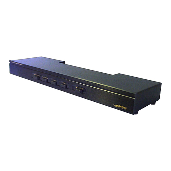
Audioplex AT-4 설치 매뉴얼
{카테고리_이름} Audioplex AT-4에 대한 설치 매뉴얼을 온라인으로 검색하거나 PDF를 다운로드하세요. Audioplex AT-4 2 페이지. At series speaker selectors with automatic purepath
Audioplex AT-4에 대해서도 마찬가지입니다: 제품 정보 (2 페이지)

AT-4 SPEAKER SELECTOR WITH AUTOMATIC LOAD PROTECTION
Your AT-4 Speaker Selector allows simultaneous operation of up to 4 pairs of 8 and 16 Ohm speakers.
Automatic load protection circuits assure that the amplifier will always "see" a load of 4 Ohms or higher, no matter
what combination of speakers is turned on.
The built-in protection circuit operates with switch pairs, permitting hookup choices for maximum power to
your most frequently used speakers (up to 2 pairs). More information can be found under INSTALLATION below .
The left and right channels are completely separate to assure safe operation with any type of amplifier,
including those with isolated grounds (bridging outputs).
Other AT-4 features include power handling capability of up to 40 Watts RMS continuous (120 Watts audio)
power, and push to connect rear panel terminals with large openings to handle up to 3/16" diameter wire.
Your AT-4 also comes with our THERMO-TEK CIRCUIT PROTECTION, which is a carefully crafted, ultra safe
protection circuit. The circuit is sonically transparent and insertion is less than 50 milliohms. This circuit features a
protectant soft reset. To reset, correct the faulty condition, or if due to overpowering, the volume control should be
turned down and the unit allowed to cool.
If advantageous to do so, choose which speakers you wish to operate at highest power according to the
following information
Speaker selector switch "pairs" are used to switch 4 Ohm resistors in the circuit when both switches are ON
at the same time. #1 and #2 switches are one pair, and #3 and #4 are the other . If 1 & 3, 1&4, 2&3, or 2&4 are the
only switches "ON", no resistor is inserted in the circuit so the full amplifier output is coupled to the selected
speakers. When any additional speakers are turned on, resistance is inserted in series with them in order to keep the
amplifier load at 4 Ohms or higher. Coupling to any speaker is always direct when only one switch is "ON".
Inputs are provided for two amplifiers, AMP A and amp B. The selector switch on the front panel directs the
chosen amplifier to all outputs. Determine which of the two amplifiers you wish to wire to A and B, or if only one
amplifier is used, connect it to the AMP A input. To make connection, strip about 1/4" of insulation from the wire
end, twist any loose strands together tightly so that no loose ends stick out to cause problems with short circuits.
Make the connection by inserting the wire end into the wire hole and tighten the retaining screw. Make sure the metal
conductor contacts the stripped part of the wire, not the insulation, and that there are no loose strands to cause
possible short circuits. Observe polarity when making connections, making sure + goes to +, - to -. and that the
channels are not crossed. Improper connections can cause the system to be inoperative, or less than optimum
sonically (note that the INPUT connector blocks are green and the OUTPUT connector blocks are black). Following the
same precautions, connect the speaker wires to the appropriate AT-4 terminals marked "SPEAKERS".
The AT-4 rubber feet provide a non-marring, stable mount to permit convenient placement. Allow room for
adequate ventilation around the switchbox, as it can become quite warm if operating at high power with the protective
resistors switched in. Do not place on surfaces easily damaged by heat.
CAUTION: Do not apply audio power in excess of 100 Watts per channel when the internal impedance
matching resistors are switched in! Damage to components caused by excessive power application is not covered by
warranty.
INSTALLATION MANUAL
TECHNOLOGY
INSTALLATION
OPERATION
2002 - 2/26/02
