DAPAudio TAS-2400 매뉴얼 - 페이지 8
{카테고리_이름} DAPAudio TAS-2400에 대한 매뉴얼을 온라인으로 검색하거나 PDF를 다운로드하세요. DAPAudio TAS-2400 18 페이지.
DAPAudio TAS-2400에 대해서도 마찬가지입니다: 매뉴얼 (18 페이지)

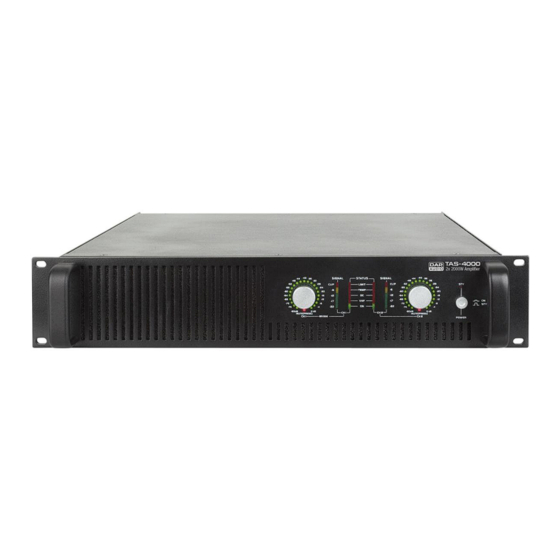
Frontpanel
1. Channel 1 Input Attenuator.
Use to attenuate the input signal of channel 1.
2. Channel 1 volume scale indicator.
This indicator displays the volume attenuation of Channel 1.
3. Channel 1 clip LED.
Illuminates at the clipping threshold. Continuous illumination also indicates that ACL (Active Clip
Limiting) protection circuitry is engaged.
4. Channel 1/2 VHF LEDs.
Indicates that channel 1 or 2 are in VHF protection mode.
5. Channel 1/2 Protect LEDs.
Indicate that channel 1 or 2 are in protection mode.
6. Parallel Mode LED.
Indicates that the amplifier is in parallel mode.
7. Channel 1/2 TEMP LEDs.
These LEDs will light if the temperature of CH1 or CH2 exceeds 95
8. Channel 2 clip LED.
Illuminates at the clipping threshold. Continuous illumination also indicates that ACL (Active Clip
Limiting) protection circuitry is engaged.
9. Channel 2 volume scale indicator.
This indicator displays the volume attenuation of Channel 2.
10. Channel 2 Input Attenuator.
Use to attenuate the input signal of channel 2.
11. Power LED.
Indicates that AC power is connected and the amplifier is turned on.
12. Air entrance.
TAS Series amplifiers are cooled by two, rear-mounted fans, Cool air flows over the heat sinks and
exhausts through the rear grills, Make sure these outlets remain clear to allow unrestricted air flow.
13. Channel 1 output level indicator.
Indication range: -22dB to +6dB.
14. Channel 1/2 ON LEDs.
Indicate that channel 1 or 2 are active.
15. Bridge Mode LED.
Indicates that the amplifier is in parallel mode.
16. Channel 2 output level indicator.
Indication range: -22dB to +6dB.
17. AC Power Switch.
This is the main Power switch. Press to turn the amplifier on.
C.
o
6
Fig. 2
