Belimo TR24-SR 빠른 시작 매뉴얼 - 페이지 2
{카테고리_이름} Belimo TR24-SR에 대한 빠른 시작 매뉴얼을 온라인으로 검색하거나 PDF를 다운로드하세요. Belimo TR24-SR 4 페이지. Rotary actuator for 2-way and 3-way characterised control valves

TRY24-SR
Product features
Mode of operation
Simple direct mounting
High functional reliability
Combination valve actuators
Electrical installation
Wiring diagrams
Information
• Connect via safety isolation transformer.
• Parallel connection of other actuators possible.
Note performance data for supply.
Dimensions [mm]
Dimensional drawings
Further documentation
2 / 2
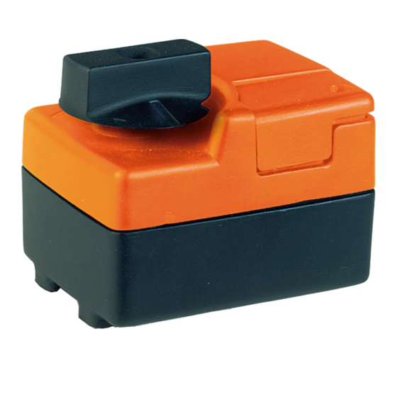
Rotary actuator AC/DC 24 V, 2 Nm
The actuator is controlled with a standard modulating signal of DC 0 ... 10 V and travels to the
position defined by the control signal.
Straightforward direct mounting on the ball valve with only one screw. The mounting position in
relation to the ball valve can be selected in 90°
Manual operation with lever possible (the gearing is disengaged for as long as the self-resetting
Manual override
lever is pressed).
The actuator is overload-proof and automatically stops when the end stop is reached.
The actuator switches off for seven seconds in the case of blocking, then attempts to restart. If
the blocked condition persists, the actuator attempts to restart once every two minutes a total of
15 times and subsequently once every two hours.
Refer to the valve documentation for suitable valves, their permitted media temperatures and
closing pressures.
Standard
–
+
!
1
2
3
Y
Direction of rotation R
(standard) with switch
position on the right
• The complete range of water solutions
• Data sheets for ball valves
• Installation instructions for actuators or ball valves, respectively
• Notes for project planning (hydraulic characteristic curves and circuits, installation regulations,
commissioning, maintenance, etc.)
T5-TRY24-SR • en • v1.1 • 05.2010 • Subject to changes
Y
DC 0 ... 10 V
Control of controller
steps.
Override control (frost protection circuit)
–
+
Y
DC 0 ... 10 V
c
d
Control of controller
1
2
3
Y
Rotary
c
d
actuator
Rotary valve
A – AB = 100%
1
A – AB = 0%
0
22
84
. .
.
.
. .
.
.
www.belimo.com
