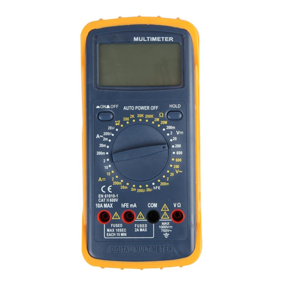
Duratool D03143 빠른 시작 매뉴얼 - 페이지 7
{카테고리_이름} Duratool D03143에 대한 빠른 시작 매뉴얼을 온라인으로 검색하거나 PDF를 다운로드하세요. Duratool D03143 8 페이지.
Duratool D03143에 대해서도 마찬가지입니다: 매뉴얼 (8 페이지)

connection will be indicated as well.
Note: When the display shows the overrange symbol "1", a higher range must be
selected.
MEASURING RESISTANCE
•
Connect the black test lead to the "COM" jack and the red test lead to the "VΩ"
jack.
Note: The polarity of the red test lead is positive.
•
Set the range switch to the desired "Ω" range.
•
If the current magnitude to be measured is unknown beforehand, select the
highest range.
•
Connect the test leads across the load to be measured, before reading the display.
•
For resistance measurements >1MΩ, the meter may take a few seconds to
stabilise the reading. This is normal for high-resistance measurement.
•
When the input is not connected, i.e. an open circuit, the symbol "1" will be
displayed as an overrange indicator.
Note: Before measuring in-circuit resistance, be sure that the circuit under test has all
power removed and all capacitors fully discharged.
CONTINUITY TEST
•
Connect the black test lead to the "COM" jack and the red test lead to the "VΩ"
jack.
Note: The polarity of the red test lead is positive.
•
Set the range switch to the "
•
Connect the test leads across the load to be measured.
•
If the circuit resistance is lower than about 30 ± 20Ω, the built-in buzzer will sound.
DIODE TEST
•
Connect the black test lead to the "COM" jack and the red lead to the "VΩ" jack.
Note: The polarity of the red test lead is positive.
•
Set the range switch to the "
•
Connect the red test lead to the anode or the diode to be tested and the black test
lead to the cathode.
•
The meter will shows the approximate forward voltage drop of diode. If the
connections are reversed, "1" will be shown on the display.
TRANSISTOR TEST (W/MULTIFUNCTION ADAPTOR)
•
Set the range switch to the "hFE" range.
•
Connect the adaptor to the "COM" jack and the "hFE" jack. Do not reverse the
connection.
•
Identify whether the transistor is NPN or PNP type and locate the emitter, base
and collector lead. Insert the lead of the transistor to be tested into the proper
holes of the transistor test socket of the adaptor.
•
The LCD will show the approximate hFE value.
MEASURING TEMPERATURE (W/MULTIFUNCTION ADAPTOR)
•
Set the range switch to the "°C" range.
•
Connect the adaptor to the "COM" jack and "°C" jack. Do not reverse the
connection.
" range.
" range.
7
