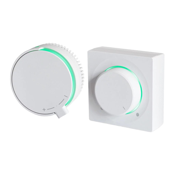
Darco ERO-32MN-2 사용 설명서 - 페이지 6
{카테고리_이름} Darco ERO-32MN-2에 대한 사용 설명서을 온라인으로 검색하거나 PDF를 다운로드하세요. Darco ERO-32MN-2 8 페이지. Electronic motor speed controller

EN
Table 1a. Supported produced created by DARCO
PK1
Device steered
-
base position
0
TH150-T
0
TH150
0
TH200
0
THP200
0
THP250
0
THP300
0
THP350
1
TH400
1
TH500
1
ANeco1-II
4
ANeco2-II
4
ANeco3-II
4
GCKV150
5
GCKV200
5
SIGNALING
Table 2. Starting procedure (with confirmation of type of device selected):
Signaling
LED light flashes green.
LED light flashes red.
LED light flashes yellow.
Table 3. Operating statuses of connected and correctly functioning controller:
Signaling
LED light lights green.
LED light flashes green.
LED light is off.
SIGNALING OF EMERGENCY SITUATIONS
Table 4. Singaling of incorrect values of PK1 and PK2 code switches (fig.1 pos.10):
Symptom of malfunction
LED light flashes green.
LED light flashes yellow.
LED light flashes red.
Table 5. Signalling of incorrect levels of voltage supplied:
Symptom of malfunction
LED light flashes:
3 x red,
1 x yellow
LED light flashes:
2 x red,
1 x yellow.
LED light flashes:
1 x red,
1 x yellow.
MAINTENANCE
No maintenance required.
PK2
LR
LG
LT
n
min
-
[1]
[1]
[1]
[rev/min.]
0
-
-
-
4
1
1
1
90
5
1
1
2
90
6
1
1
3
90
7
1
2
1
90
8
1
2
2
90
9
1
2
3
90
0
1
2
4
90
1
1
3
1
40
2
1
3
2
40
5
2
2
1
610
6
2
2
2
610
7
2
2
3
610
5
3
2
1
1000
6
3
2
2
1000
Description
Signaling the family of device steered (see table 1/column LR).
Signaling the group of device steered (see table 1/column LG).
Signaling the type of device steered (see table 1/column LT).
Description
Actual rotation speed of steered device varies from the one set on controller no more than 40% of value set.
Actual rotation speed of steered device varies from the one set on controller in the range of 40% to 80% of value set.
Controller is in standby mode (knob is turned completely le ).
Cause
Coding switches have not been positioned to steer any device (base position 00).
Coding switches have been positioned to steer a device that is not supported.
Internal damage of controller.
Cause
Too high voltage connected to the controller.
Too low voltage connected to the controller.
Internal damage of controller.
Table 1b. Additional controller functions
n
max
Function
[rev/min.]
-
regulated voltage source 5V
500
regulated voltage source 10V
300
270
where:
380
PK1, PK2 - selected number on coding switch
380
LR
- number of LED diode flashes green (describing family of devices)
280
LG
- number of LED diode flashes red (describing group of devices)
262
LT
- number of LED diode flashes orange (describing type of device)
180
n
- minimal rotation speed
180
min
n
- maksymalmaximal rotation speed
1500
max
U
- minimal voltage R at the R output
1500
min
U
- maximum voltage R at the R output
1500
max
2250
2300
Table 6. Others:
Symptom of malfunction
LED light is off in spite of
setting rotation speed.
LED light lights red, but motor
of steered device does not
rotate.
LED light lights red, but motor
of steered device turns on for
30 seconds and then switches
off for 60 seconds.
PK1
PK2
LR
LG
LT
-
-
[1]
[1]
[1]
9
8
0
0
0
9
9
0
0
0
Cause
1. Incorrect supplied voltage polarity.
2. S+ cable damaged.
3. S- cable damaged.
4. Controller power feeder damaged.
5. Internal damage of controller.
1. R cable damaged.
2.Steered device has been blocked mechanically.
3. Internal damage of controller.
1. I cable damaged.
2. Internal damage of controller.
U
U
min
max
[V]
[V]
0
5
0
10
