Aplisens APM-2 장치 설명서 - 페이지 7
{카테고리_이름} Aplisens APM-2에 대한 장치 설명서을 온라인으로 검색하거나 PDF를 다운로드하세요. Aplisens APM-2 17 페이지. Smart electronic differential pressure transmitters

5.
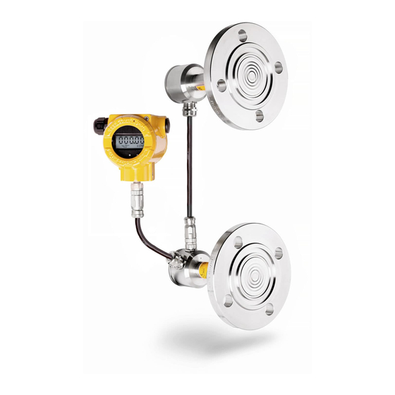
TRANSMITTER DESIGN
The modular differential pressure transmitters consist of: central unit HUB two pressure
transmitters PC1, PC2.
The basic central unit HUB components are: housing made of 316 (1.4401) stainless steel or
aluminium, electronic module. Transmitters in aluminium, steel enclosures are allowed for II
and III group.
The PC1 and PC2 transmitters consist of housing and a measuring head converting the
signal from the head to the output signal. PC1 and PC2 transmitter housings are made of 316
or 304 steel and are approved for Group II and III.
6.
ELECTROSTATIC HAZARDS
The paint, plastic nameplate and diaphragm seals coated with PTFE form a non-conducting
layer applied on a conducting base of enclosure or diaphragm seals. Transmitters with this
design in a dust-explosion zone should be installed in a place where electrostatic charging is
impossible, in particular by contact with electrically charged dust falling off or blown from
neighboring devices.
When performing connection and maintenance activities in the hazardous area, the
possibility of electrostatic discharge should be eliminated. Do not wipe the transmitter dry.
7.
SPECIAL CONDITIONS OF USE
a) In hazardous zones, transmitters with painted aluminum enclosures as well as
transmitters equipped with equipped with plastic nameplate and PTFE-coated
diaphragm separator components should be installed in way that prevents
electrostatic charging specified in accordance with point 6.
b) An intrinsically safe transmitter version with surge arrester, marked on the
nameplate as "SA" does not meet the requirements of clause 10.3 of EN 60079-11
(500Vrms). This must be taken into account when installing the device.
c) If the membrane separator contains titanium elements, it must be protected against
mechanical impact.
d) The circuit behind the galvanic separation in the central unit does not comply with
the requirements of clause 6.3.6 of PN 60079-11:2012 for solid insulation to the
housing. Potential equalisation must be applied between the transmitter central unit
and transmitters PC1 and PC2.
e) The power supply for the transmitter shall comply with overvoltage category II (or
better) according to EN 60664-1.
f) Flameproof joints are not intended to be repaired.
Revision 01.A.001/2022.09
EN.IX.APM.2
7
