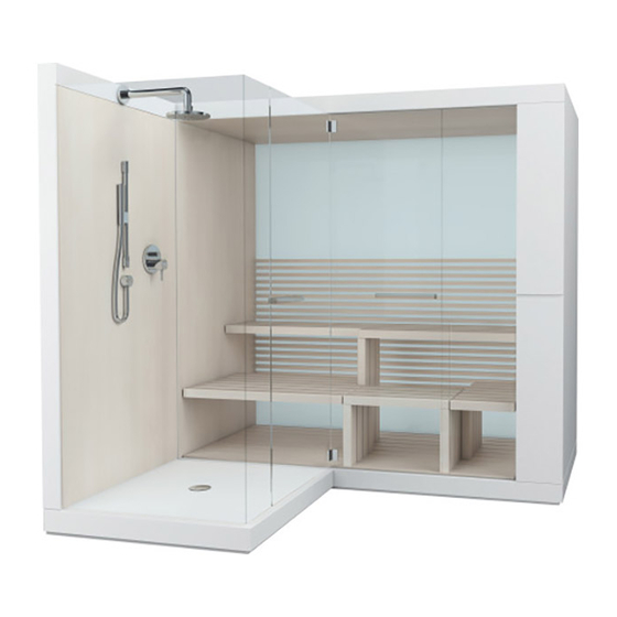
DURAVIT Inipi 사전 설치 - 페이지 8
{카테고리_이름} DURAVIT Inipi에 대한 사전 설치을 온라인으로 검색하거나 PDF를 다운로드하세요. DURAVIT Inipi 10 페이지.
DURAVIT Inipi에 대해서도 마찬가지입니다: 사용 설명서 (19 페이지)

Pre-installation
INSTALLATION POSITION / INSTALLATION ROOM
> Ensure installation position fulfils following criteria
Temperature range
Ceiling height
Necessary area
Doors / External access > Ensure doors or other access openings are
Static Load
Floor
Wall
Room air
dehumidification
Minimum clearances
WATER CONNECTION (ONLY INIPI AMA)
> Install water connection in designated zone
Warm water
Cold water
Working pressure
> Install water drain in designated zone (DN50)
8
SAUNA_VID_Inipi_Inipi-Ama/15.07.7
15 - 40 °C
min. 2350 mm
see drawing for zone
large enough to cater for pool transport
dimensions and there is sufficient
manoeuvring room.
Note! If you are unsure or there are
differences, always ask an expert.
> Screed according to DIN 18560
Flexural Strength class F4
Minimum thickness 45 mm
> Floor covering suitable for
1.5 N/mm
point load
2
completely level,
Floor covering permanent
Inipi Ama: water-resistant floor covering
completely straight,
at right angle to floor
Air inlet and exhaust available and sufficient
Ensure
installation
room
has
dehumidification
(Air exhaustconnection possible)
The minimum clearances to the structure
must be observed to ensure the optimum
function of the sauna and to avoid damage to
the structure.
Front 1000 mm
Top 130 mm
Side 25 mm
Bottom 20 mm
DN 15 (1/2")
DN 15 (1/2")
min. 0,1 MPa, max. 1,0 MPa (1MPa = 10 bar)
ELECTRICAL INSTALLATION OF REMOTE CONTROL
CHARGING STATION
> Install switched contact plug outside protection area 0 - 2.
SAUNA ELECTRICAL INSTALLATION
Electricity Supply
Maximum rated power 6.6 KW
380-415V 3PH N PE
sufficient
50/60Hz
max. 6,6kW
delay fuse protection 3x16A
separate residual-current circuit
breaker (IN = 30 mA)
Lay electrical feed with 3 L, N, PE
Exposed cable length 1000 mm
Install circuit breaker:
3 pole circuit breaker I
separate Residual Current Circuit Breaker (RCCB) (Iδn = 30 mA), that
disconnects all poles of Equipement from mains
RADIO CONNECTION (RECOMMENDATION)
> Lay two antenna terminals with coaxial connector for Modulation FM
(UKW) and AM (MW).
6 0
0
0
6 0
1
2
0
3N ~ 380-415V 50/60Hz
power supply box
/
L1
/
L2
/
L3
/
N
/
PE
= 16 A
N
/
L1
/
L2
/
L3
/
N
/
PE
