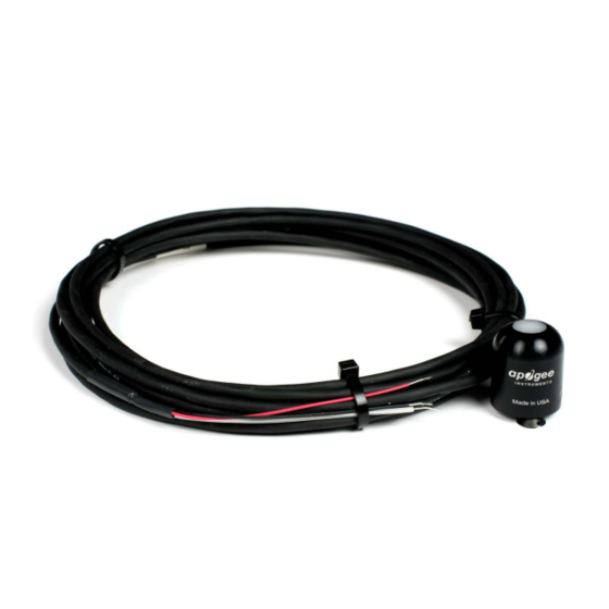
Apogee SP-214 소유자 매뉴얼 - 페이지 11
{카테고리_이름} Apogee SP-214에 대한 소유자 매뉴얼을 온라인으로 검색하거나 PDF를 다운로드하세요. Apogee SP-214 19 페이지. Pyranometer
Apogee SP-214에 대해서도 마찬가지입니다: 소유자 매뉴얼 (18 페이지)

OPERATION AND MEASUREMENT
Connect the sensor to a measurement device (meter, datalogger, controller) capable of measuring and displaying
or recording a 4-20 mA signal. In order to maximize measurement resolution and signal-to-noise ratio, the input
range of the measurement device should closely match the output range of the pyranometer. DO NOT connect the
sensor to a power source greater than 24 V DC.
VERY IMPORTANT:
Apogee changed the wiring colors of all our bare-lead sensors in March 2018 in
conjunction with the release of inline cable connectors on some sensors. To ensure proper connection to your
data device, please note your serial number or if your sensor has a stainless-steel connector 30 cm from the
sensor head then use the appropriate wiring configuration listed below. With the switch to connectors, we also
changed to using cables that only have 4 or 7 internal wires. To make our various sensors easier to connect to
your device, we clip off any unused wire colors at the end of the cable depending on the sensor. If you cut the
cable or modify the original pigtail, you may find wires inside that are not used with your particular sensor. In
this case, please disregard the extra wires and follow the color-coded wiring guide provided.
Wiring for SP-214 with Serial Numbers 9898 and above
Wiring for SP-214 with Serial Numbers range 0-9897
Black: Ground (from sensor signal and output power)
Red: Input power (7-24 V DC)
White: 4-20 mA signal output
Clear: Shield/Ground
Red: Input power
Black: Input ground
Clear: Shield/ground
Green: Signal ground
White: 4-20 mA signal output
