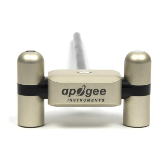
Apogee SN-500-SS 소유자 매뉴얼 - 페이지 10
{카테고리_이름} Apogee SN-500-SS에 대한 소유자 매뉴얼을 온라인으로 검색하거나 PDF를 다운로드하세요. Apogee SN-500-SS 19 페이지. Net radiometer

OPERATION AND MEASUREMENT
The SN-522 has a Modbus output, where the four components of net radiation, along with net values (net
shortwave, net longwave, and net radiation), are returned in digital format. Measurement of SN-522 net
radiometers requires a measurement device with a Modbus interface that supports the Read Holding Registers
(0x03) function.
Wiring
The Green wire should be connected to Ground to enable RS-485 communication, or it should be connected to 12
V power for RS-232 communication. Text for the White and Blue wires above refers to the port that the wires
should be connected to.
Sensor Calibration
All Apogee Modbus net radiometers (model SN-522) have sensor-specific calibration coefficients determined
during the custom calibration process. Coefficients are programmed into the sensors at the factory.
Modbus Interface
The following is a brief explanation of the Modbus protocol instructions used in Apogee SN-522 net radiometers.
For questions on the implementation of this protocol, please refer to the official serial line implementation of the
Modbus protocol:
http://www.modbus.org/docs/Modbus_over_serial_line_V1_02.pdf
Modbus protocol specification:
Further information can be found at:
Overview
The primary idea of the Modbus interface is that each sensor exists at an address and appears as a table of values.
These values are called Registers. Each value in the table has an associated index, and that index is used to identify
which value in the table is being accessed.
Sensor addresses
Each sensor is given an address from 1 to 247. Apogee sensors are shipped with a default address of 1. If using
multiple sensors on the same Modbus line, the sensor's address will have to be changed by writing the Slave
Address register.
http://www.modbus.org/docs/Modbus_Application_Protocol_V1_1b3.pdf
http://www.modbus.org/specs.php
White: RS-232 RX / RS-485 Positive
Blue: RS-232 TX / RS-485 Negative
Green: Select (Switch between RS-232 and RS-485)
Black: Ground
Red: Power +12 V
(2006) and the general
(2012).
