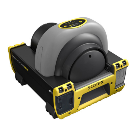
Dürr NDT ScanX Discover HC 빠른 시작 지침 - 페이지 2
{카테고리_이름} Dürr NDT ScanX Discover HC에 대한 빠른 시작 지침을 온라인으로 검색하거나 PDF를 다운로드하세요. Dürr NDT ScanX Discover HC 4 페이지. Mobile computed radiography system
Dürr NDT ScanX Discover HC에 대해서도 마찬가지입니다: 빠른 시작 지침 (4 페이지)

Box contents
Unpacking
As listed below, each ScanX System is shipped in a single carton
containing the ScanX main assembly and associated accessory
kit. Unpack each component of the ScanX and inspect for physi-
cal damage such as scratched panels, damaged connectors, etc.
If any damage is noted, immediately notify your authorized
dealer so corrective action can be taken. Save all cartons and
packing materials to protect the ScanX in the event of future
transport or shipping.
Included System Components
Each ScanX system consists of the indicated main assembly
and accessory kit as listed. Refer to the TECHNICAL DATA
section of the Operator's Manual included on the supplied CD
Disk for ratings and identification for specific ScanX models.
Verify that all listed items were received. If any item is missing,
notify your dealer.
Important:
Make sure to read and follow the Operator's Manual included as a PDF file on the supplied CD Disk to ensure that your ScanX
gives the highest level of service. Please note that the Operator's Manual is also available on the website (www.scanx-ndt.com).
Setup & operation
ScanX Imaging Software and Device Drivers Installation
The user must provide appropriate and compliant computer hardware where ScanX View or an authorized third-party imaging software is
installed. In addition, USB device drivers must also be installed to operate ScanX. When using ScanX View, these drivers are automatically
installed during the software installation. When using a third-party imaging software, drivers are installed via the Setup program provided on
the CD disk included with ScanX. Normally, this program runs automatically when the CD is inserted into the drive for the first time.
If not, run the Setup program located in the root directory of the CD (typically D:\AutoRun.exe).
Important: The fuse must be installed in order to operate the ScanX via the battery.
Battery Fuse Installation. Install the supplied 5A fuse as follows:
1. Insert the fuse cartridge into the fuse holder hole.
2. Secure the fuse by twisting the fuse cap 1/4 turn clockwise.
ScanX Connections. As shown by the illustration at right, connecting the ScanX for operation
consists of the following
1. Connect to the computer via supplied USB cable.
2. Connect to power source via supplied line cord.
Important: The built-in battery must always be charged prior to using for the first time.
Make sure the CHARGE LEVEL indicator illuminates green prior to use.
Battery Charging. Charge the battery as follows:
1. Place the Main Power switch to the ON (I) position and press the BATTERY ON/OFF
switch to the OFF position.
2. Allow the battery to charge for a full 3 hours before using for the first time and on
subsequent uses to reach the full operational power level.
3. Verify that the CHARGE LEVEL indicator illuminates green by removing the AC power and
depressing the BATTERY ON/OFF switch to the ON position. If okay, turn the BATTERY
ON/OFF switch to the OFF position.
ScanX Operation. Operate the ScanX connected to a properly set up computer as follows:
1. Perform one of the following steps depending on operating power desired.
a. When operating from the battery, depress the BATTERY switch and verify the CHARGE
LEVEL indicator shows an adequate power level.
b. When operating from AC Mains, place the Main Power switch to ON and set the
BATTERY ON/OFF switch to the ON position (flush with the panel). Make sure the
CHARGE LEVEL indicator illuminates green.
2. Press the READY switch to turn ON the ScanX.
3. Verify that the READY indicator illuminates.
4. Activate the scanner via the Imaging Software.
5. Verify that all track status indicators illuminate green.
6. Minimize exposure to ambient light and insert the PSP into the ScanX inlet with the
sensitive (front) side of PSP towards the ScanX.
7. Verify that all track status indicators illuminate yellow.
8. Observe that the scanned PSP exits through the scanner arch.
Manufactured by Air Techniques for:
DÜRR NDT GmbH & Co. KG
Höpfigheimer Straße 22
74321 Bietigheim-Bissingen, Germany
Phone: +49 7142 99381-0 · Fax: +49 7142 99381-299
www.scanx-ndt.com
System Components
Model
ScanX Discover Imaging Plate Scanner
Quick Start Instructions
Accessory Kit containing:
3-meter USB cable
Fuse Kit (5A, 250VAC, Fuse; qty 2)
CD Disk containing Drivers and
Operator's Manual
Country specific Mains cable
IEC Connector
The fuse must be installed in order to operate the ScanX via the battery.
Page 2 of 4
ScanX
Discover HR-B
2138100009
2138100301
2138100043
Type B USB Connector
Note:
The Main Power Switch is the
AC Mains disconnect device.
Line Cord Plug
From AC Mains Outlet
IMPORTANT:
5A, 250VAC 3AG SLO-BLO Battery Fuse
BATTERY ON/OFF Switch
IMPORTANT:
Unless the ScanX is in use under battery power, the ON/OFF
(BATTERY) switch must always be in the OFF position to
prevent battery discharge.
CHARGE LEVEL Indicator
ERASER
Eraser
Switch
Scanner Track
Status
Status Indicators
Indicator
P/N D5421DQB, Rev A (2138100302 ) - May 2017
ScanX
Discover HC-B
2138100011
2138100301
2138100043
to ScanX
Type A USB
Connector to
Computer
Main Power
Switch (I/0)
READY
Switch
Ready/
Standby
Status
Indicator
