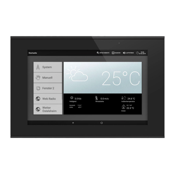
Elsner 71200 설치 지침
{카테고리_이름} Elsner 71200에 대한 설치 지침을 온라인으로 검색하거나 PDF를 다운로드하세요. Elsner 71200 2 페이지. Control center
Elsner 71200에 대해서도 마찬가지입니다: 빠른 시작 매뉴얼 (2 페이지)

EN
Brief installation instructions
CasaConnect KNX Control Center
Article number 71200
The manual with additional information about commissioning,
functions and operation of the control center CasaConnect
KNX can be downloaded from www.elsner-elektronik.de in the
menu area "Service/Downloads".
Installation, testing, operational start-up and troubleshooting should
only be performed by an authorised electrician.
CAUTION!
Live voltage!
There are unprotected live components inside the device.
• Inspect the device for damage before installation. Only put undamaged
devices into operation.
• Comply with the locally applicable directives, regulations and provisions for
electrical installation.
• Immediately take the device or system out of service and secure it against
unintentional switch-on if risk-free operation is no longer guaranteed.
Use the device exclusively for building automation and observe the operating in-
structions. Improper use, modifications to the device or failure to observe the oper-
ating instructions will invalidate any warranty or guarantee claims.
Operate the device only as a fixed-site installation, i.e. only in assembled condition
and after conclusion of all installation and operational start-up tasks, and only in the
surroundings designated for it.
Elsner Elektronik is not liable for any changes in norms and standards which may
occur after publication of these operating instructions.
Preparing the installation location
The device may only be installed and operated in dry indoor rooms.
Avoid condensation.
Preparing the control unit
The CasaConnect KNX can be installed in 2 standard sockets, however, a double
socket has more space for the cables.
The CasaConnect KNX is delivered assembled. The device, which comprises the
display unit and support plant, therefore has to be dismantled. After installation and
connection, the device is reassembled in the reverse order.
2
1
CasaConnect KNX installation • Version: 07.09.2021 • Technical changes and errors excepted. • Elsner Elektronik GmbH • Sohlengrund 16 • 75395 Ostelsheim • Germany • www.elsner-elektronik.de • Technical Service: +49 (0) 7033 / 30945-250
CasaConnect KNX installation
Step 1 Display from below
The display unit is screwed to the
support plate from below. Loos-
en the screws.
Step 2 Display from the side
Pull the display unit forward from
the lower area by simultaneously
pushing from below against the
two catches, and hang it from the
top edge.
The display can now be re-
moved.
Display from above
Detail view: Notices
and mounts of the
display unit.
1
2
3
When handling the display unit, take care with the loudspeaker (3). This is magnetic
and connected with sensitive cables.
All dimensions in mm
Step 3 Support plate as drill template
Use the support panel as a drill template. Place it over the position of the two stand-
ard switch boxes and mark the 4 drill holes for the 4 fixing screws.
For maintenance, the covers can be carefully levered out in order to gain access to
the screws.
Pass all connection cables through the top socket and the top opening of the support
plate.
Connection and installation of the control unit
Cover the support plate screw connection with the caps provided.
Hang the display unit at the top of the support plate and fold it down (step 2). The
display snaps in but also has to be secured with 2 screws (step 1).
Technical data, control center CasaConnect KNX
Casing
Glass, plastic
Colour
black
Assembly
Flush-mounted (in 2 standard switch sockets
or a double socket)
Display rear
1 Network cable connection
(optional)
2 KNX bus and auxiliary voltage
connection
3 Loudspeaker with cover
Step 4 Support panel on wall
Screw the support plate to the
wall using 4 screws. Use suitable
fastening material for the base. 4
countersunk cross-slot screws
(WN57, 3.5x35mm, galvanised)
with matching anchors (S5) are
supplied.
After
commissioning
the
screws should be covered with
the supplied covers.
Display rear connections
Connect KNX (red + / black -) and
24 V DC auxiliary voltage (yellow
+ / white -). For a cable network
connection, connect the network
cable to the Ethernet socket.
1 Auxiliary volt-
+ yellow
age
2 Auxiliary volt-
-
white
age
5 KNX
+ red
6 KNX
-
black
1
