COOK Vari-Flow VFRSC 설치, 운영 및 유지보수 매뉴얼
{카테고리_이름} COOK Vari-Flow VFRSC에 대한 설치, 운영 및 유지보수 매뉴얼을 온라인으로 검색하거나 PDF를 다운로드하세요. COOK Vari-Flow VFRSC 2 페이지. Remote speed controller
®
This publication contains installation, operation and main-
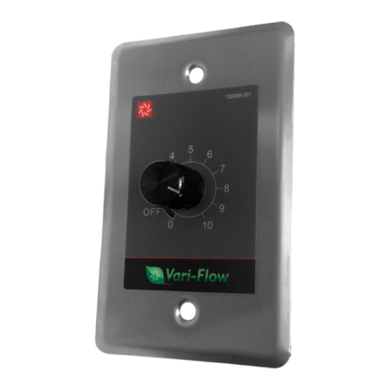
tenance instructions for the standard Vari-Flow
Speed Controller.
Carefully read this publication prior to any
installation or maintenance procedure.
Any additional publications can be obtained from Loren
Cook Company through any of the following:
• lorencook.com
• 417-869-6474 ext. 166
For information and instructions on special equipment, con-
tact Loren Cook Company Customer Service Department at
417-869-6474.
Storage
If the controller is stored for any length of time prior to instal-
lation, store controller in the original packaging inside from the
weather and keep temperature between -22°F to 122°F (-30°C
to 50°C).
Installation
The VFRSC can be mounted in a electrical box with the two
screws provided. This device requires a 24VAC/DC power
supply. VFRSC is UL Listed when mounted in UL Listed en-
closure. Minimum transformer output of 1VA.
Location and Maintenance
Consider the following points while choosing a location for
the Vari-Flow Remote Speed Controller.
• Less than 100 feet of wiring to motor or to VFABK.
• Install the controller indoors.
• Do not place the controller on the floor.
• Maintain a temperature between 30°F to 110°F (-1°C to
43°C). A temperature beyond this range may cause conden-
sation and sweating of metal parts.
• Maintain a low humidity, dry, and clean atmosphere. Ensure
that the controller is not in the path of blowing dust, rain, or
snow.
Operation
This device outputs a 0-10v signal voltage. The dial does not
indicate voltage, but a range of available voltage from max to
min. Vari-Flow motors operate on a 2-10V signal. Below 2V,
the motor stops but is still powered.
VFRSC IO&M
REMOTE SPEED CONTOLLER
INSTALLATION, OPERATION AND MAINTENANCE MANUAL
Wiring
Remote
®
All wiring should be in accordance with local ordinances and
the National Electrical Code, NFPA 70. Ensure the power sup-
ply (voltage, frequency, and current carrying capacity of wires)
is in accordance with the motor nameplate. When paired with
Air Balance Kit (VFABK), see Air Balance Kit supplemental in-
stallation instructions for wiring.
1
Vari-Flow
24VAC/DC
0-10VDC
Common
Remote Speed Controller
VFRSC
®
P000283-001