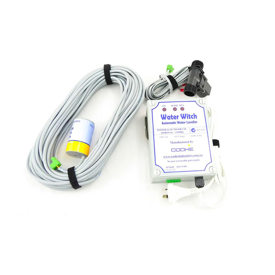
Cooke Water Witch 설치 매뉴얼 - 페이지 2
{카테고리_이름} Cooke Water Witch에 대한 설치 매뉴얼을 온라인으로 검색하거나 PDF를 다운로드하세요. Cooke Water Witch 6 페이지. A fully automatic pool and spa water levelling system
Cooke Water Witch에 대해서도 마찬가지입니다: 설치 및 설정 매뉴얼 (12 페이지)

Control Box
Mount the control box at lease 1.2 meters off the ground using the steel bracket provided.
Solenoid
The Solenoid must be installed in the water supply line using the flow direction arrow indicated on
the solenoid body.
Sensor
Refer to the diagrams 5 & 6 on page 3 for mounting of the Sensor.
The suggested method of plumbing is two 40mm class 9 PVC pipes plumbed through the pool wall and returned to the
pump and filter area.
These pipes are placed approximately 300mm below normal water level and finished off in the pool with push in
eyeballs to match the other pool fittings. The pipes are usually run along the suction and return trench and elbowed up
near the pool equipment.
IMPORTANT
These pipes must remain below the water level by a minimum of 200mm (more is better) until elbowed into a vertical
position. A minimum vertical height of 300mm above the top of the pool is required for both pipes.
When light is on status is as follows:
ON
- Unit Operating
SENSE
FILL
- The unit has switched on the solenoid after
sensing low water and is filling the pool
INSTALLATION GUIDE
Pool Installers Sensor Pipe & Fill Plumbing
THREE MAIN COMPONENTS
Control Box
Co-ordinates the above items with visual
ndicators of status shown in diagram below.
Level Sensor
Our patented levelling sensor designed to
fit into 40mm class 9 pipe.
Solenoid
Solenoid with indicator arrow that controls
the flow of water.
- In Sense mode waiting for drop in water
