AUSTRALIAN MONITOR AM1600 운영 매뉴얼 - 페이지 15
{카테고리_이름} AUSTRALIAN MONITOR AM1600에 대한 운영 매뉴얼을 온라인으로 검색하거나 PDF를 다운로드하세요. AUSTRALIAN MONITOR AM1600 20 페이지. Professional audio power amplifier
AUSTRALIAN MONITOR AM1600에 대해서도 마찬가지입니다: 브로셔 (4 페이지), 사양 (2 페이지), 소유자 매뉴얼 (8 페이지)

5. Bridge Mode
The term BRIDGE is used when two independent
amplifier channels are used to drive the same load. The
load is in series (a bridge) between the two amplifier
channels.
Channel A is used as the "dominant" channel and its
output is in phase with the input signal, and channel
B has to have its phase reversed so it is exactly 180
out of phase with the input signal.
As two amplifiers with a phase difference of 180
now driving the load you will now have double the
voltage into the load. This means you will now have four
times the power into that load. The output can now be
considered as an active balanced output.
A common use of an amplifier in BRIDGE mode is for
driving 70 volt & 100 volt distribution lines. In BRIDGE
mode, The AM1600 can produce in excess of 114 volts
into a line impedance of 8 ohms (1600 watts) and in
excess of 90 volts into a line impedance of 4 ohms
(2100 watts).
Equally the units can be used in bridge mode to provide
the correct voltage/power requirements for an applica-
ble load.
As shown in Figure 6, there are four steps in setting up
your AM1600 amplifier for running it in BRIDGE mode.
Whilst the amplifier is off,
1. Connect the signal source to the Channel-A female
Figure 6 Bridge Mode Speaker Connection
input XLR.
2. Loop from Channel-A male XLR to Channel-B fe-
male input XLR with a Reverse Phase Lead.
A reverse Phase Lead is wired:
Channel-A
Pin-1 to
Pin-2 to
0
Pin-3 to
3. Connect your load between the red binding post
0
are
output terminals, where the positive side of the
load is connected to the Channel-A output and the
negative side of the load goes to the Channel-B
output . There are no further connections required.
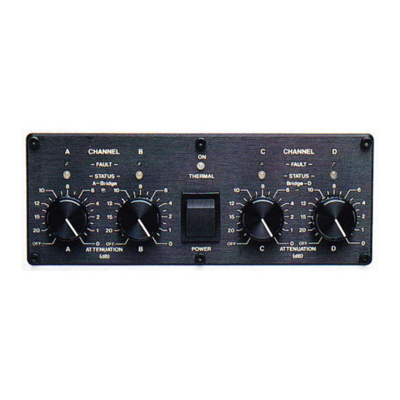
4. Turn the attenuators on both channels fully clock-
wise (0dB - no attenuation).
You can also source the output from the Channel-A
SPEAKON output connector where Channel-A will be
on the pin marked 1+ and Channel-B will be on the pin
marked 2+.
NOTE: You should check after market manufactured
Speakon interconnecting speaker leads before
connecting them to your amplifier. Some leads are
manufactured for specific purposes, or specific use,
and may have pins shorted inside the connector. Any
speakon lead with shorted pins will obviously short the
output of your amplifier (either to ground, or output to
output - be careful).
Bridge Mode 15
Channel-B
Pin-1
Pin-3
Pin-2
