4RF Aprisa XE 빠른 시작 매뉴얼 - 페이지 2
{카테고리_이름} 4RF Aprisa XE에 대한 빠른 시작 매뉴얼을 온라인으로 검색하거나 PDF를 다운로드하세요. 4RF Aprisa XE 2 페이지. Radio link
4RF Aprisa XE에 대해서도 마찬가지입니다: 기술 문서 (15 페이지), 빠른 시작 매뉴얼 (2 페이지)
1. Check the box contents
Each Aprisa XE radio is shipped to you in a single box containing the following items:
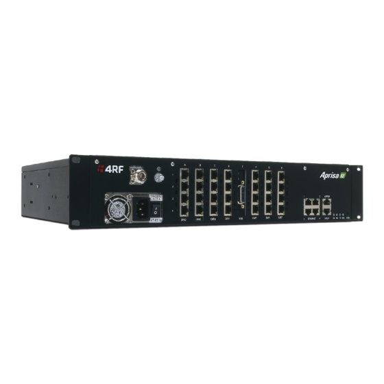
Aprisa XE Radio
Accessory kit containing the following:
• Rack mount bracket [x2]
• Bracket fastening screw [x4]
(countersink PZD2)
• Nylon washer [x6]
• Setup cable with
RJ-45 to DB-9 adaptor
• Ethernet cable spare
• Power cable
12 VDC, 24/48 VDC or AC
Note: The Aprisa XE radio operates within frequency bands that require a site license be issued by the radio
regulatory authority with jurisdiction over the territory in which the equipment is being operated. It is the
responsibility of the user, before operating the equipment, to ensure that where required the appropriate license
has been granted and all conditions attendant to that license have been met.
Hereby, 4RF Limited declares that the Aprisa XE digital radio is in compliance with Directive 2014/53/EU. The full
text of the EU declaration of conformity is available at the internet address http://www.4rf.com/library/en
Configuration Sheet
Commissioning Form
• Interface Slot
Blanking plate [x2]
• M6 caged nut [x4]
• M6 x 8 (PZD3) [x6]
• M2 Allen key
(for fascia and lid screws)
• 100 mm cable tie [x20]
2. Install the radio terminals
1.
Confirm that the correct interface cards are fitted.
2.
Fasten the mounting brackets to the radio terminal and mount it in the rack
3.
Connect the radio terminal's earth stud to the rack with the Earth cable using
the 8 mm spanner
3. Connecting antennas and power to the radio terminals
1.
Before connecting power to the radio, ensure that the antenna is connected to the antenna port. If the antenna is not available, terminate the Antenna port
with a N type male 50 ohm termination (10 Watts min, up to 3 GHz). The two radios can be interconnected on the bench with two N type male 50 ohm 30 /
40 dB attenuators (10 Watts min, up to 3 GHz) on the antenna ports, interconnected with a N type coaxial cable. Do not directly connect the two radio antenna
ports without attenuation of at least 60 dB. The receiver can be damaged if signals greater than -20 dBm are applied to the antenna port.
2. Connect the external power supply to the radio terminal.
3.
For DC power supplies, switch on the external power supply.
For AC power supplies, turn the radio power switch on.
4.
Confirm that your antenna, feeder cable, weatherproofing, earthing and
lightning protection are correctly installed.
5.
Connect the flexible coaxial jumper cable between the lightning protector and
radio antenna connector.