Bender RCM420 Series 기술 게시판 - 페이지 4
{카테고리_이름} Bender RCM420 Series에 대한 기술 게시판을 온라인으로 검색하거나 PDF를 다운로드하세요. Bender RCM420 Series 6 페이지. Digital ground fault monitor / ground fault relay grounded and high-resistance grounded ac systems
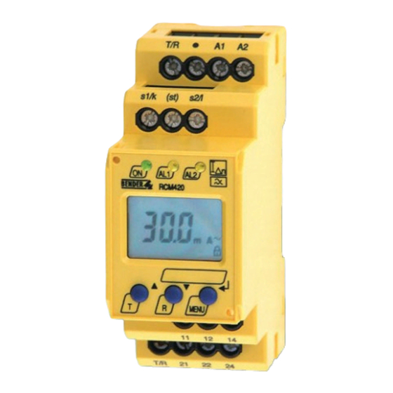
Ground Fault Monitor RCM420
Technical data
Insulation coordination acc. to IEC 60664-1 / IEC 60664-3
Rated insulation voltage
Rated impulse voltage / pollution degree
Protective separation (reinforced insulation) between
Voltage test according to IEC 61010-1
Supply voltage
Supply voltage U
S
Power consumption
Measuring circuit
External measuring current transformer
Load
Rated insulation voltage (measuring current transformer)
Operating characteristic acc. to IEC 62020
Rated frequency
Measuring range
Relative percentage error
Display accuracy
Response values
Rated residual operating current I
Δn1
Rated resiudal operating current I
Δn2
Hysteresis
Specified time
Starting delay t
Response delay t
(alarm)
on2
Response delay t
(prewarning)
on1
Delay on release t
off
Operating time t
at I
= 1 x I
ae
Δn
Δn1 / 2
at I
= 5 x I
Operating time t
ae
Δn
Δn1 / 2
Response time t
an
Recovery time t
b
Number of restart cycles
Cable lengths for current transformers
Single wire ≥ AWG 20 (0.75 mm
)
2
Single wire, twisted ≥ AWG 20 (0.75 mm
Shielded cable ≥ AWG 22 (0.5 mm
2
Recommended cable
(shielded, shield on one side connected
to terminal l of the RCM420, not connected to earth)
Connection
Displays, memory
Display range, measuring value
Relative percentage error
Measured-value memory for alarm value
Password
Latching behavior
ON / OFF / CON (Latching / Non-latching / Remains latched on return from power loss)
4
(A1, A2) - (k / l, T / R) – (11, 12, 14) – (21, 22, 24)
see ordering details
W - , WR - , WS - series
(prewarning)
50 - 100 % x I
(alarm)
10 mA - 10 A (30 mA)*
10 - 25 % (15 %)*
0 - 10 s (0,5 s)*
0 - 10 s (0 s)*
0 - 10 s (1 s)*
0 - 99 s (1 s)*
t
= t
an
0 . . . 3.2 ft (0 - 1 m)
)
0 . . . 32.8 ft (0 - 10 m)
2
)
0 . . . 131 ft (0 - 40 m)
J-Y(ST)Y min. 2 x 0.8
screw terminals
0 - - 30 % / ± 2 digit
data record measured values
off / 0 - 999 (off)*
Inputs / outputs
250 V
Cable length for external test / reset button
2.5 kV / III
Switching elements
Number of switching elements
Operating principle
2.21 kV
Electrical service life under rated operating conditions
Contact data acc. to IEC 60947-5-1
Utilization category
≤ 3 VA
Rated operational voltage
Rated operational current
Minimum contact load
Environment / EMC
68 Ω
800 V
EMC
Type A
Operating temperature
42 - 2000 Hz
Climatic class acc. to IEC 60721
3 mA - 16 A
Stationary use (IEC 60721-3-3)
0 - - 20 %
Transport (IEC 60721-3-2)
± 15 %
Long-time storage (IEC 60721-3-1)
Classification of mechanical conditions IEC 60721
Stationary use (IEC 60721-3-3)
(50 %)*
Transport (IEC 60721-3-2)
Δn2
Long-time storage (IEC 60721-3-1)
Connection
Connection
rigid / flexible
Multi-conductor connection (2 conductors with the same cross section)
rigid / flexible
Stripping length
≤ 180 ms
Tightening torque
≤ 30 ms
Other
+ t
ae
on1 / 2
≤ 300 ms
Operating mode
0 - 100 (0)*
Position of normal use
Degree of protection, internal components (IEC 60529)
Degree of protection, terminals (IEC 60529)
Enclosure material
Flammability class
DIN rail mounting acc. to
Screw mounting
Standards
Instruction leaflet
Weight
( )* factory setting
3 mA - 16 A
0 - 32 ft (0 - 10 m)
2 SPDT contacts
normally energized or normally deenergized(*)
10.000 switching operations
AC-13
AC-14
DC-12
DC-12
DC-12
230 V
30 V
24 V
110 V
5 A
3 A
1 A
0.2 A
1 mA at AC / DC ≥ 10 V
IEC 62020: 2003-11
- 25 °C - + 55 °C
3K5 (except condensation and formation of ice)
2K3 (except condensation and formation of ice)
1K4 (except condensation and formation of ice)
screw terminals
AWG 24 - 12 / 24 - 14
AWG 24 - 14 / 24 - 14
8 - 9 mm
0.5 - 0.6 Nm
continuous operation
IP30, NEMA 1
IP20, NEMA 1
polycarbonate
UL94V-0
IEC 60715
2 x M4 with mounting clip
IEC 62020
TGH1410
≤ 150 g
220 V
0.1 A
3M4
2M2
1M3
any