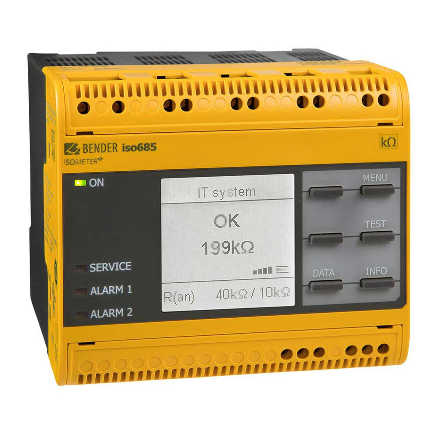
Bender ISOMETER iso685-D-P-CN 빠른 시작 매뉴얼 - 페이지 2
{카테고리_이름} Bender ISOMETER iso685-D-P-CN에 대한 빠른 시작 매뉴얼을 온라인으로 검색하거나 PDF를 다운로드하세요. Bender ISOMETER iso685-D-P-CN 8 페이지.

ISOMETER® iso685...-CN
与 IT 系统断开 !
在装置进行绝缘或者电压测试之前,绝缘监视仪必
须与 IT 系统断开, 并且保证测试持续时间
设备可能会损坏
警告
。
安装
考虑相邻设备的最小距离:侧面 0 毫米,顶部 20 毫米,底部
20 毫米!
导轨安装 :
每个设备需要 3 个安装夹(其中的 2 个为独立包装) ,安装在
DIN 导轨上,保证安全和安装紧固。
螺丝安装
手动或者使用工具安装 3 个配套的安装夹 (2 个为一组单独
包装) , 安装夹伸出外壳。 通过三个 M4 螺丝装置固定装置 (无
沉头螺钉)如下图所示。
螺丝安装 / Screw mounting
54 mm
连接
根据设备的接线图对设备进行布线,请参考技术参数。连接装
置后,安装上、下端子盖板 !
电击危险 !
额定电压上升至 1000V 的电压可能瞬间出现在端子
L1/+...L3/–上
。
危险
用设备之前,确保已经正确安装端子盖板
应用线路保护 !
符合标准 DIN VDE 0100-430, 线路保护将用于电源
电压
。
警告
由于短路造成的伤害、火灾和设备损坏!
当耦合端子 L1/+, L2, L3/- 连接到≤ 690 V 的被
监视IT 系统时, 设备防止短路就必须符合标准IEC
提醒
60364-4-43:2008,如果采用这样的接线方式,可
以把短路风险降到最低
故障检验的接线方式
2
否则,
。
108 mm
72 mm
直接接触可能会引起触电
。
。
推荐采用短路检验和接地
。
。
Disconnect from the IT system!
The insulation monitoring device must be disconnected
from the IT system before insulation or voltage tests at
CAUTION
the installation and must remain so for the duration of
the test. Otherwise the device may be damaged.
Installation
Consider a minimum distance to adjacent devices: lateral 0 mm,
top 20 mm, bottom 20 mm!
DIN rail mounting:
Snap all 3 mounting clips delivered with the device (2 of them
packed separately) onto the DIN rail in such a way that a safe and
tight fit is ensured.
Screw mounting
Install the three accompanying mounting clips (2 of them are
packed separately) manually or by means of a tool in a way that
they protrude beyond the enclosure. Fix the device by means of
three M4 screws (no counter sunk screw) as shown in the follow-
ing pictures.
导轨安装 / DIN rail mounting
Connection
Wire up the device according to the wiring diagram taking ac-
count of the technical data. After connecting the device, install
the enclosed upper and lower terminal cover!
Risk of electric shock!
A nominal voltage of up to 1000 V may be present at the
在使
terminals L1/+...L3/–. Direct contact with these will
DANGER
likely result in electrocution. Make sure the terminal
covers are properly mounted and clicked in before
putting the device into operation.
Apply line protection!
According to DIN VDE 0100-430 a line protection shall
be provided for the supply voltage.
CAUTION
Danger of injury, fire and damage to property due to
a short circuit!
When coupling the terminals L1/+, L2, L3/- to the IT sys-
WARNING
tem ≤690 V to be monitored, devices for protection
against a short-circuit can be omitted according to
IEC 60364-4-43:2008 if the wiring is carried out in such a
way as to reduce the risk of a short-circuit to a mini-
mum. The use of short-circuit proof and earth-fault
proof wiring is recommended.
iso685_D00022_06_Q_CNEN/10.2016
