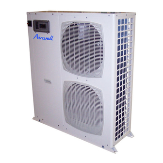
Airwell PAC HT 12-6 엔지니어링 데이터 매뉴얼 - 페이지 8
{카테고리_이름} Airwell PAC HT 12-6에 대한 엔지니어링 데이터 매뉴얼을 온라인으로 검색하거나 PDF를 다운로드하세요. Airwell PAC HT 12-6 20 페이지. High temperature air-to-water heat pumps

General Hydraulic Layout for a Type 3 (*) Installation
1
Stop valve
3
Filter or sludge trap
4
Relief valve
5
3-way valve - Domestic hot water
6
Domestic hot water tank
7
Safety devices
8
Recycling circulating pump (optional)
9
Circulation pump
10
Mixing tank
Layout 3 :
This layout is also recommended for heating installations with wide operating water flow variations (radiator thermostatic valves present in the system). Minimum
system volume is guaranteed by a mixing tank (10). Take care when calculating the volume of water in the installation and only take account of 50% of the mixing
tank's volume.
Example :
For a useful volume of 100 litres the actual mixing tank volume will be 200 litres.
The flow adjustment valve
(11)
is used to balance the flow in heating mode and domestic hot water mode to always ensure optimum PAC HT operation.
8
HW
1
1
6
1
1
5
1
11
3
1
1
12
1
8
3
7
CW
1
14
1
15
9
13
1
4
1
10
11
Flow regulating valve
12
Expansion tank
13
In-line heater
14
Bleed
15
Safety valve
HW : Hot Water
CW : Cold Water
*
Installation components not supplied
1
