Bender B 94 012 018 매뉴얼 - 페이지 6
{카테고리_이름} Bender B 94 012 018에 대한 매뉴얼을 온라인으로 검색하거나 PDF를 다운로드하세요. Bender B 94 012 018 8 페이지.

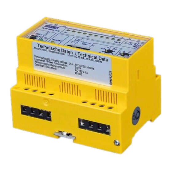
RCM470LY / RCM475LY
Ansprechcharakteristik nach IEC 60755 ...................................................................................Typ A
Bemessungsansprechdifferenzstrom I
................................................................ 10 mA...10 A
Δn
Bemessungsansprechdifferenzstrom I
RCM470LY-72 ................................... 100 mA...100 A
Δn
Ansprechverzögerung t
, einstellbar ................................................................................. 0...10 s
V
Genauigkeit der Ansprechverzögerung ..........................................................................+ / - 20 %
Bemessungsfrequenz (RCM470LY) ............................................................................. 40...400 Hz
Bemessungsfrequenz (RCM475LY) ................................................................................50...60 Hz
Ansprechabweichung ........................................................ 40...400 Hz, 50...60 Hz: 0...-25 %
.............................................................................................................400...1000 Hz: 10...-25 %
Hysterese ............................................................................................. ca. 25 % vom Ansprechwert
= 0 s) .................................................................. ≤ 250 ms
Ansprechzeit t
bei I
= 1 x I
(t
Δn
Δn
an
V
= 0 s) .................................................................... ≤ 20 ms
Ansprechzeit t
bei I
= 5 x I
(t
Δn
Δn
an
V
Anzahl der Messkanäle ....................................................................................................................1
Anzeigen
LED-Laufpunktanzeige ...................................................................................................0...100 %
LEDs ............................................................................................................................ Betrieb, Alarm
Eingänge / Ausgänge
TEST- und RESET-Taste .............................................................................................. intern / extern
Kabellänge externe TEST- und RESET-Taste ....................................................................... ≤ 10 m
Stromquelle für externes Messinstrument ...............................................................DC 0...400 μA
Bürde ................................................................................................................................... 12,5 kΩ
Leitungslängen für Messstromwandler (nur RCM470LY)
Einzeldraht ≥ 0,75 mm² ......................................................................................................0...1 m
Einzeldraht verdrillt ≥ 0,75 mm² ..................................................................................... 0...10 m
Schirmleitung ≥ 0,5 mm² ................................................................................................ 0...40 m
Empfohlene Leitung
geschirmt, Schirm einseitig an L des RCM470 und nicht erden)................. J-Y(ST)Y, min. 2 x 0,8
Schaltglieder
Schaltglieder ..............................................................................................................1 x 2 Wechsler
Arbeitsweise, einstellbar ........................................................................Ruhestrom / Arbeitsstrom
Elektrische Lebensdauer .....................................................................................12000 Schaltspiele
Kontaktbemessungsspannung ........................................................................ AC 250 V / DC 300 V
Einschaltvermögen .........................................................................................................AC / DC 5 A
Ausschaltvermögen ............................................................................ 2 A, AC 230 V, cos phi = 0,4
...........................................................................................................0,2 A, DC 220 V, L / R = 0,04 s
Fehlerspeicherung ...............................................................................................................ein / aus
Allgemeine Daten
EMV Störfestigkeit ............................................................................................................ EN 61543
EMV Störaussendung ............................................................................................... EN 61000-6-4
Schockfestigkeit IEC 60068-2-27 (Gerät in Betrieb) ...................................................15 g / 11 ms
Dauerschocken IEC 60068-2-29 (Transport) ................................................................. 40 g / 6 ms
Schwingungsbeanspruchung IEC 60068-2-6 (Gerät in Betrieb) .......................1 g / 10...150 Hz
Schwingungsbeanspruchung IEC 60068-2-6 (Transport) .................................2 g / 10...150 Hz
Umgebungstemperatur, bei Betrieb................................................................... -10 °C...+ 55 °C
Umgebungstemperatur, bei Lagerung ............................................................... -40 °C...+ 70 °C
Klimaklasse nach IEC 60721-3-3 ................................................................................................3K5
Betriebsart .....................................................................................................................Dauerbetrieb
Einbaulage ............................................................................................................................beliebig
Anschlussart ............................................................................................................Reihenklemmen
Anschlussvermögen
Starr / flexibel ...........................................................................................0,2...4 / 0,2...2,5 mm²
Flexibel mit Aderendhülse ohne / mit Kunststoffhülse ........................................ 0,25...2,5 mm²
Leitergrößen (AWG) ............................................................................................................24...12
Schutzart, Einbauten (IEC 60529) ..............................................................................................IP30
Schutzart, Klemmen (IEC 60529) ...............................................................................................IP20
Gehäusetyp .....................................................................................................................X475, X470
Gehäusematerial .......................................................................................................... Polycarbonat
Schraubbefestigung ................................................................................................................2 x M4
Schnellbefestigung auf Hutprofilschiene ......................................................................... IEC 60715
Einbau in Installationsverteiler nach ................................................................................DIN 43871
Entflammbarkeitsklasse ...................................................................................................... UL94V-0
Gewicht ................................................................................................................................ ≤ 350 g
6
Operating characteristic acc. to IEC 60755 ............................................................................Type A
Rated residual operating current I
........................................................................10 mA...10 A
Δn
Rated residual operating current I
RCM470LY-72 .......................................... 100 mA...100 A
Δn
Response delay t
, adjustable .............................................................................................0...10 s
V
Accuracy of response delay .............................................................................................+ / - 20 %
Rated frequency (RCM470LY).......................................................................................40...400 Hz
Rated frequency (RCM475LY).........................................................................................50...60 Hz
Relative percentage error ...................................................40...400 Hz, 50...60 Hz: 0...-25 %
............................................................................................................400...1000 Hz: 10...-25 %
Hysteresis ................................................................................. approx. 25 % of the response value
= 0 s) ................................................................. ≤ 250 ms
Response time t
at I
= 1 x I
(t
Δn
Δn
an
V
= 0 s) ................................................................... ≤ 20 ms
Response time t
at I
= 5 x I
(t
Δn
Δn
an
V
Number of measuring channels ...................................................................................................... 1
Displays
LED bar graph indicator .................................................................................................. 0...100 %
LEDs ........................................................................................................................ Power On, Alarm
Inputs / outputs
TEST and RESET button ........................................................................................internal / external
Cable length external TEST and RESET button .................................................................... ≤ 10 m
Current source for external measuring instrument .................................................DC 0...400 μA
Load .....................................................................................................................................12.5 kΩ
Cable lengths for measuring CTs (RCM470LY only)
Single wire ≥ 0.75 mm2..................................................................................................... 0...1 m
Single wire, twisted ≥ 0.75 mm2 .................................................................................... 0...10 m
Shielded cable ≥ 0.5 mm2 ............................................................................................... 0...40 m
Recommended cable (shielded, shield on one side
connected to terminal l of the RCM470, not connected to earth) ................ J-Y(ST)Y min. 2 x 0.8
Switching elements
Number of switching elements ...............................................................1 x 2 changeover contacts
Operating principle, adjustable ....................................................... N / C operation/N/O operation
Electrical endurance, number of cycles ...................................................................................12000
Rated contact voltage .......................................................................................AC 250 V / DC 300 V
Limited making capacity ................................................................................................ AC / DC 5 A
Breaking capacity .................................................................................2 A, AC 230 V, cos phi = 0,4
..........................................................................................................0.2 A, DC 220 V, L / R = 0.04 s
Fault memory behaviour ...................................................................................................... On / Off
General data
EMC immunity .................................................................................................................. EN 61543
EMC emission ............................................................................................................ EN 61000-6-4
Shock resistance IEC 60068-2-27 (during operation) ................................................. 15 g / 11 ms
Bumping IEC 60068-2-29 (during transport) ............................................................... 40 g / 6 ms
Vibration resistance IEC 60068-2-6 (during operation) .................................... 1 g / 10...150 Hz
Vibration resistance IEC 60068-2-6 (during transport) .....................................2 g / 10...150 Hz
Ambient temperature, during operation ............................................................- 10 °C...+ 55 °C
Ambient temperature, when stored ...................................................................- 40 °C...+ 70 °C
Climatic category IEC 60721-3-3 ................................................................................................3K5
Operating mode .............................................................................................. continuous operation
Mounting ....................................................................................................................... any position
Connection ............................................................................................................... screw terminals
Connection properties
rigid / flexible ........................................................................................... 0.2...4 / 0.2...2.5 mm²
flexible with ferrules without / with plastic collar ................................................0.25...2.5 mm²
Conductor sizes (AWG) .......................................................................................................24...12
Protection class, internal components (IEC 60529) ..................................................................IP30
Protection class, terminals (IEC 60529) .....................................................................................IP20
Type of enclosure ............................................................................................................ X475, X470
Enclosure material ......................................................................................................polycarbonate
Screw mounting .....................................................................................................................2 x M4
DIN rail mounting acc. to ...................................................................................................IEC 60715
Flammability class .............................................................................................................. UL94V-0
Standards ...........................................................................................................................IEC 62020
Weight ................................................................................................................................. ≤ 350 g
TBP401003deen / 09.2008
