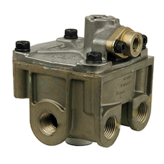
BENDIX ATR1DC ANTILOCK TRACTION RELAY 매뉴얼 - 페이지 7
{카테고리_이름} BENDIX ATR1DC ANTILOCK TRACTION RELAY에 대한 매뉴얼을 온라인으로 검색하거나 PDF를 다운로드하세요. BENDIX ATR1DC ANTILOCK TRACTION RELAY 12 페이지. Antilock traction relay valve
BENDIX ATR1DC ANTILOCK TRACTION RELAY에 대해서도 마찬가지입니다: 설치 지침 (4 페이지)

The ATR-1DC
™
valve also has an auxiliary control port that
permits coordination of the traction function with an air
suspended tag axle on a 6x2 vehicle. The auxiliary control
port(21) connects to the air suspension control valve. If a
traction event occurs and the tag axle is down and loaded
the ATR-1DC
™
valve is able to reduce air pressure in the tag
axle air bags. Lowering pressure in the tag axle air bags
increases the loading on the drive axle and further assists in
eliminating wheel spin on acceleration.
OPERATION
Reservoir air pressure is constantly present at the traction
solenoid. When the electronic controller detects wheel
spin it energizes the solenoid and in response the solenoid
opens momentarily. While the solenoid is open, air is
delivered through internal passages to double check valve
diaphragm "A".
Note:
If the optional auxiliary port is in use, traction
solenoid air pressure is also delivered to the air
suspension system of the "tag" or non-drive axle.
This signal pressure is used to exhaust some of
the air pressure from the suspension bags on the
tag axle. This causes some of the vehicle weight
(carried by the tag axle) to shift to the drive axle
further enhancing the traction control.
The check valve diaphragm flexes in response and seals
the passage to the open exhaust of the secondary delivery
of the brake valve. Once past double check valve "A", air
from the solenoid flows to double check valve "B" which
flexes and seals the passage to the open exhaust of the
primary delivery of the brake valve. Air flowing around
double check valve "B" moves through the rest of the valve
in the same manner as a normal service brake application
and is delivered out the delivery ports of the ATR-1DC
to the antilock modulators near the rear wheels they serve.
When the electronic controller de-energizes the ATR-1DC
valve's traction solenoid, air between the solenoid and the
double check valve "A", including the air signal sent to the
suspension system through the optional auxiliary port,
returns to the solenoid and is exhausted. Air between
double check valve "A" and "B" is exhausted from the
secondary circuit of the brake valve. Air between the relay
piston and double check valve "B" is exhausted from the
primary circuit of the brake valve. Air in the service brakes
is exhausted at the main ATR-1DC
PREVENTIVE MAINTENANCE
GENERAL
Perform the tests and inspections presented at the
prescribed intervals. If the ATR-1DC
as described, or leakage is excessive, it should be repaired
or replaced with a new or genuine Bendix remanufactured
unit, available at any authorized parts outlet.
™
valve
™
™
valve's exhaust port.
™
valve fails to function
EVERY 3 MONTHS, 25,000 MILES OR 900 OPERATING
HOURS
1. Remove any accumulated contaminates and visually
inspect the exterior for excessive corrosion and
physical damage.
2. Inspect all air lines connected to the ATR-1DC
signs of wear or physical damage. Replace as
necessary.
3. Test air line fittings for excessive leakage and tighten or
replace as necessary.
4. Perform the Leakage Test described in this manual.
EVERY YEAR, 100,000 MILES, OR 3,600 OPERATING
HOURS
1. Perform the Operation and Leakage Tests described in
this manual.
WARNING! PLEASE READ AND FOLLOW
THESE INSTRUCTIONS TO AVOID
PERSONAL INJURY OR DEATH:
When working on or around a vehicle, the following
general precautions should be observed at all times.
1. Park the vehicle on a level surface, apply the
parking brakes, and always block the wheels.
Always wear safety glasses.
2. Stop the engine and remove ignition key when
working under or around the vehicle. When
working in the engine compartment, the engine
should be shut off and the ignition key should be
removed. Where circumstances require that the
engine be in operation, EXTREME CAUTION should
be used to prevent personal injury resulting from
contact with moving, rotating, leaking, heated or
electrically charged components.
3. Do not attempt to install, remove, disassemble or
assemble a component until you have read and
thoroughly understand the recommended
procedures. Use only the proper tools and observe
all precautions pertaining to use of those tools.
4. If the work is being performed on the vehicle's air
brake system, or any auxiliary pressurized air
systems, make certain to drain the air pressure from
all reservoirs before beginning ANY work on the
vehicle. If the vehicle is equipped with an AD-IS
air dryer system or a dryer reservoir module, be
sure to drain the purge reservoir.
5. Following
the
recommended procedures, deactivate the electrical
system in a manner that safely removes all
electrical power from the vehicle.
6. Never exceed manufacturer's recommended
pressures.
7. Never connect or disconnect a hose or line
containing pressure; it may whip. Never remove a
component or plug unless you are certain all
system pressure has been depleted.
™
valve for
vehicle
manufacturer's
™
7
