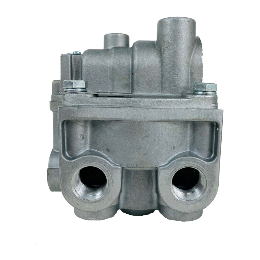
BENDIX BP-R1 BOBTAIL PROP RELAY VALVE 매뉴얼 - 페이지 8
{카테고리_이름} BENDIX BP-R1 BOBTAIL PROP RELAY VALVE에 대한 매뉴얼을 온라인으로 검색하거나 PDF를 다운로드하세요. BENDIX BP-R1 BOBTAIL PROP RELAY VALVE 11 페이지. Bobtail proportioning relay valve

9. Remove and discard the o-ring (12) from the relay
piston (13).
10. Remove and discard dust shield (16), if fi tted, and the
retaining ring (15) from the valve cover (2), then remove
and discard the exhaust piston (17 or 17A).
11. Remove and discard the exhaust piston o-ring (18) and
the exhaust diaphragm (19), if fi tted.
12. Remove and discard the service piston (20) and its
o-ring (21) from the valve cover (2).
13. Remove the spring (22) and spring cage (23) from the
valve cover (2). Discard the spring and retain the spring
cage.
14. Use shop air at the control port to extract the blend back
piston from the valve cover (2). Retain the blend back
piston (24), then remove and discard both o-rings (25
& 26).
15. Remove and retain the proportioning piston (28) from
the valve cover (2), then remove and discard both
o-rings (27 & 29).
16. While holding the inlet valve seat (32) in place, remove
and discard the retaining ring (30) from the proportion-
ing piston (28).
17. Remove the inlet valve seat (32), the inlet valve (33),
and the valve spring (34) from the proportioning piston
(28), then remove and discard the o-ring (31) from the
valve seat (32). Discard the valve and spring (33 & 34)
also.
18. Remove and discard the exhaust cover screw (36) and
exhaust cover (37).
CLEANING & INSPECTION
1. Using mineral spirits or an equivalent solvent, clean and
thoroughly dry all metal parts. Do not damage bores
with metal tools.
2. Wash all non-metallic components (key nos. 4, 12, 17,
20, 23, 24, 28, 32) in a soap and water solution making
certain to rinse and dry thoroughly.
3. Inspect the interior and exterior of all metal parts that
will be reused for severe corrosion, pitting and cracks.
Superfi cial corrosion and/or pitting on the exterior por-
tion of the body (1) and cover (2) is acceptable. Replace
the entire valve if the interior of the body or cover exhibit
signs of corrosion or pitting.
4. Inspect each non-metallic component for cracks, wear
or distortion. Replace the entire valve if these conditions
are found.
5. Inspect the bores of both the body (1) and cover (2)
for deep scuffi ng or gouges. Replace the entire valve if
either are found.
8
6. Make certain the air channel running between the top
surface of the body (1) and its supply port is clear and
free of obstruction.
7. Make certain all air channels and exhaust passages in
the valve cover (2) are clear and free of obstruction.
8. Inspect the pipe threads in the body (1) and valve cover
(2). Make certain they are clean and free of thread
sealant.
9. If the valve was equipped with a relay piston spring
(14), inspect it for signs of corrosion, pitting and cracks.
Replace as necessary.
10. Inspect all air line fi ttings for corrosion and replace
as necessary. Make certain to remove all old thread
sealant before reuse.
ASSEMBLY
1. Prior to assembly, lubricate all o-rings (identify by using
Figure 11), seals, and pistons as well as body and cover
bores, using the lubricant provided with the Bendix
maintenance kit. Use all of the lubricant and spread it
evenly on the rubbing surfaces.
2. Install the o-ring (31) on the inlet valve seat (32).
O-RING IDENTIFICATION
KEY NO.
I.D.
5
.8620
6
1.424
11
3.487
13
3.234
18
1.356
21
1.176
25
1.112
26
.7370
27
.4120
29
.7390
31
.4890
FIGURE 11 - O-RING IDENTIFICATION
I.D. "
W"
O.D. "
O.D.
W
1.068
.103
1.630
.103
3.693
.103
3.512
.139
1.496
.070
1.316
.070
1.318
.103
.9430
.103
.5520
.070
.8790
.070
.6290
.070
