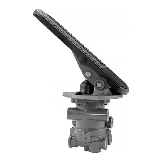
BENDIX E-12-E-15 BRAKE VALVE 매뉴얼 - 페이지 4
{카테고리_이름} BENDIX E-12-E-15 BRAKE VALVE에 대한 매뉴얼을 온라인으로 검색하거나 PDF를 다운로드하세요. BENDIX E-12-E-15 BRAKE VALVE 8 페이지. Dual brake valve

PLUNGER
SUP-1
SUP-2
FIGURE 8 - BALANCED POSITION
BALANCED: SECONDARY CIRCUIT PORTION
When the air pressure on the secondary side of the relay
piston approaches the pressure being delivered on the pri-
mary side of the relay piston, the relay piston moves closing
the secondary inlet valve preventing further air flow from the
supply line through the valve. The exhaust remains closed
as the secondary delivery pressure balances the primary
delivery pressure.
SUP-1
SUP-2
FIGURE 9 - RELEASED MODE
4
FORCE
2
DEL-1
DEL-2
EXHAUST
PLUNGER
FORCE
2
8
DEL-1
DEL-2
EXHAUST
RELEASING: PRIMARY CIRCUIT PORTION
When the force on the brake treadle is released, the me-
chanical force is removed from the graduation spring (8) and
the primary piston (2). Air pressure in the delivery circuit
moves the primary piston exhaustive valve, allowing air pres-
sure in the primary piston to exhaust through the exhaust
port.
RELEASING: SECONDARY CIRCUIT PORTION
When the brake treadle is released, air is exhausted from
the primary circuit side of the relay piston through the bleed
passage. Air pressure in the delivery side of the secondary
circuit moves the relay piston upward, opening the second-
ary exhaust valve allowing air pressure in the secondary
delivery line to exhaust out the exhaust port.
PREVENTIVE MAINTENANCE
Important: Review the warranty policy before performing
any intrusive maintenance procedures. An extended war-
ranty may be voided if intrusive maintenance is performed
during this period.
Because no two vehicles operate under identical conditions,
maintenance and maintenance intervals will vary. Experi-
ence is a valuable guide in determining the best maintenance
interval for any one particular operation.
Visually check for physical damage to the brake valve such
as broken air lines and broken or missing parts.
EVERY 3 MONTHS, 25,000 MILES OR 900 OPERATING
HOURS:
1. Remove any accumulated contaminates such as dirt
and gravel from the heel of the treadle (26), plunger (27)
plunger boot (28) and mounting plate (29).
2. Use a light oil, lubricate the treadle roller (30), roller pin
(31) and hinge pin (32).
3. Inspect the plunger boot (28) for cracks, holes or dete-
rioration and replace if necessary. Also check mounting
plate and treadle for integrity, wear and corrosion and
replace or repair as necessary.
4. Apply 2 to 4 drops of oil between plunger and mounting
plate - do not over oil!
5. Check for excessive leakage as described in the
Operation & Leakage Checks section of this manual.
EVERY YEAR, 100,000 MILES, OR 3,600 OPERATING
HOURS:
1. Perform steps 1 through 4 above.
2. Perform the operation and leakage checks described in
the Operation & Leakage Checks section of this manual.
