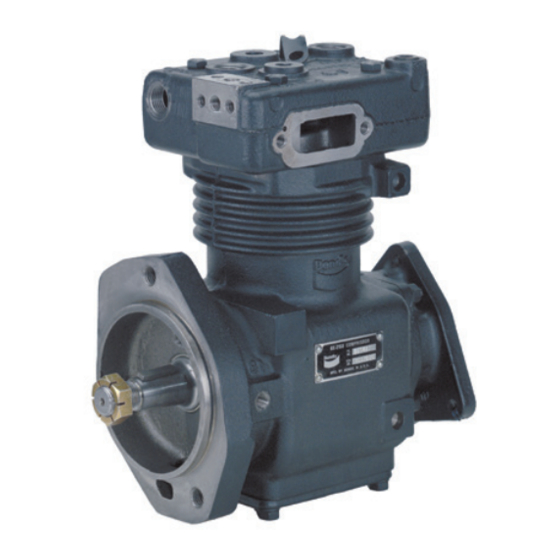
BENDIX BX-2150 설치 지침 - 페이지 3
{카테고리_이름} BENDIX BX-2150에 대한 설치 지침을 온라인으로 검색하거나 PDF를 다운로드하세요. BENDIX BX-2150 4 페이지. Compressor maintenance kit
BENDIX BX-2150에 대해서도 마찬가지입니다: 빠른 시작 매뉴얼 (4 페이지)

ASSEMBLY
Use contents contained in both kits.
1. Install the unloader stop and o-ring assembly (1 & 2)
into the threaded port on the top of the head above the
air inlet cavity. Torque to 175-225 in-lbs.
2. Turn the head over and install the unloader piston and
o-ring assembly (3 & 4) into the unloader cavity (short
stem first). Install the unloader spring (16) (small end
first) over the long stem of the unloader piston (4). Install
the inlet valve gasket (13) over the unloader spring and
rest it on the shoulder of the hole in the inlet cavity. Install
the inlet valve seat (7) on top of the inlet valve gasket
(bevel side of the valve seat up). Install inlet valve (15)
on the valve seat. Install inlet valve spring (6) on the
inlet valve. Retain with the inlet valve stop (5). Using a
spanner-type wrench torque to 840-1080 in-lbs.
3. Install the discharge valve spring (11) into the cavity of
the discharge valve stop. Install the discharge valve (8)
on top of the discharge valve spring and retain with the
discharge valve seat (14). Using a 9/16" Allen
torque to 840-1080 in-lbs.
4. Test the head for air leakage prior to installing the head
onto the compressor. Refer to "Air Leakage Tests"
section.
5. Install the cylinder head gasket (12) onto the crankcase.
Place the head in the proper position onto the crankcase
and retain with the four 5/16" cap screws. Snug all four
cap screws prior to torquing in a cross pattern to 175-
225 in-lbs.
6. Install the inlet fitting or air strainer onto the compressor.
Install the strainer gasket (10) between either
component and the compressor.
7. Replace the governor or air line from the governor onto
the compressor. If the governor is direct mounted onto
the mounting pad of the compressor, install the governor
gasket (9) between the mounting pad and the governor.
8. Connect the discharge air line to the discharge port on
the top of the head.
9. Connect the inlet and outlet water lines to the head and
refill the radiator.
CHECK FOR COMPRESSOR OPERATION
1. Start the engine and observe the system pressure
gauge to ensure the compressor is pumping. Observe
that the compressor unloads (stops pumping) at the
governor cut-out setting.
2. Make several light brake applications until the governor
cut-in setting is reached. Observe that the compressor
again begins to pump.
COMPRESSOR TESTING
Vehicles manufactured after the effective date of FMVSS
121, with the minimum required reservoir volume, must have
a compressor capable of raising air system pressure from
85-100 psi in 25 seconds or less. This test is performed
with the engine operating at maximum recommended
governed speed. The vehicle manufacturer must certify this
performance on new vehicles with appropriate allowances
for air systems with greater than the minimum required
reservoir volume.
wrench,
®
AIR LEAKAGE TESTS
Leakage past the discharge valve can be detected as follows:
Remove the discharge line and cylinder head from the
compressor and apply shop air back through the discharge
port. Coat the discharge valve seat with soapsuds. Bubble
leakage is permitted.
The unloader piston can be checked for leakage as follows:
Build up the air system to governor cut-out and shut off the
engine. Listen for escaping air at the compressor intake.
To pinpoint leakage, apply a small amount of oil around the
unloader piston. No leakage is permitted. Apply oil or soap
solution around the threads of the unloader stop assembly
on the top of the head.
3
