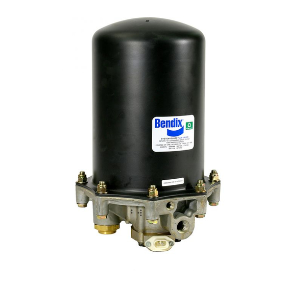
BENDIX AD-9 서비스 데이터 - 페이지 12
{카테고리_이름} BENDIX AD-9에 대한 서비스 데이터을 온라인으로 검색하거나 PDF를 다운로드하세요. BENDIX AD-9 20 페이지.

COMPRESSOR
10 AMP - 12V
5 AMP - 24V
FUSE
FIGURE 2 - AD-9 CHARGE CYCLE
4. A universal mounting plate (Pc. No. 248478) is available
to facilitate the mounting of the AD-9 air dryer to the
vehicle. It can be obtained through an authorized Bendix
parts outlet.
5. Mount the AD-9 air dryer on the vehicle using 3/8" bolts
(grade 5 min.) and washers. Torque to 25 ft. Ibs. (300
inch pounds.) After positioning and mounting the upper
bracket assembly according to the installation
requirements, torque the 5/16" nut to 80120 in. Ibs. to
tighten strap onto the shell.
CONNECTING THE AIR LINES
PURGE CONTROL LINE
1. Install a Purge Control air line having a minimum inside
diameter of 3/16 inches between the AD-9 end cover
control port and an unused unloader port on the governor.
The control line must be plumbed direct to the governor
and not in series with automatic drain valves, lubrication
systems, etc.
2. The control line should slope downward to the end cover
without forming potential water traps.
12
UNLOADER
PORT
CON
SUP
14 GA WIRE
TO IGNITION
& GROUND
GOVERNOR
SAFETY VALVE
DEL
DISCHARGE LINE
General:
Where minimum diameter are specified, larger line diameters
generally improve performance and life and reduce
temperatures, particularly in severe applications.
1. The discharge line material should be wire braided Teflon
hose, copper tubing or a combination of both.
2. The discharge line should slope downward from the
compressor discharge port to the AD-9 air dryer supply
port without forming water traps, kinks or restrictions.
Cross-overs from one side of the frame rail to the other,
if required, should occur as close as possible to the
compressor.
3. Fitting extensions must not be installed at the AD-9
supply port.
4. Discharge line lengths and inside diameter requirements
are dependent on the vehicle application and are as
follows:
CONTROL
(HIDDEN)
DELIVERY
SUPPLY
RESERVOIR
# 1
TO RESERVOIR
# 2
