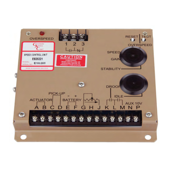
GAC ESD-5570 Series 기술 정보 - 페이지 3
{카테고리_이름} GAC ESD-5570 Series에 대한 기술 정보을 온라인으로 검색하거나 PDF를 다운로드하세요. GAC ESD-5570 Series 12 페이지. Speed control unit
GAC ESD-5570 Series에 대해서도 마찬가지입니다: 매뉴얼 (8 페이지), 매뉴얼 (8 페이지)

Adjusting Crank Termination (ESD-5556 only)
To protect the engine from harm the CRANK TERMINATION adjustment is factory set at full
CCW [Lowest Setting]. To adjust CRANK TERMINATION speed setting, rotate the CRANK
adjustment to full CW. Crank the engine and simultaneously turn the CRANK adjustment slowly
CCW until the proper crank termination speed is reached. In operation, when the cranking
termination set point is reached, the green CRANK LED will illuminate. (Cranking has
terminated).
The ESD-5556 is set for manual reset. To reinstate engine cranking, battery power must be
removed and then reapplied which will recycle the control.
Adjusting Overspeed
When the engine is running at the desired speed, push and hold the TEST button. Rotate the
OVERSPEED adjustment CCW until the red OVERSPEED LED lights and the relay energizes. Current
to the actuator will be removed and the engine will shut off.
Release the TEST button. After the engine stops, press the RESET button or remove battery
power. Restart the engine and it will return to the original speed setting. The overspeed function is
now set to approximately 10% above the requested speed.
If a different value of overspeed setting is required, raise the engine speed to the desired
overspeed value, i.e. 115%. Rotate the OVERSPEED adjustment CCW until the red OVERSPEED
LED lights and the relay enginerizes.
Always use the relay contacts provided to shut down the system by a means other than the governor or
actuator. It is recommended that an overspeed protection system be routinely tested and verified during the
Governor Speed Setting
The governed speed set point is increased by a CW rotation of the SPEED adjustment control.
Remote speed adjustment can be obtained with an optional 5K Speed Trim Control.
(See Diagram 1.)
Governor Performance
Once the engine is at operating speed and at no load, the following governor performance
adjustment can be made.
A.
Rotate the GAIN adjustment CW until instability develops. Gradually move the adjustment
CCW until stability returns. Move the adjustment one division further CCW to insure stable
performance.
B.
Rotate the STABILITY adjustment clockwise until instability develops. Gradually move the
adjustment counterclockwise until stability returns. Move the adjustment one division
further to insure stable performance (270° pot).
Technical Information
WARNING
scheduled service of equipment.
