GAC ESD-5570 Series 매뉴얼 - 페이지 2
{카테고리_이름} GAC ESD-5570 Series에 대한 매뉴얼을 온라인으로 검색하거나 PDF를 다운로드하세요. GAC ESD-5570 Series 8 페이지. Speed control unit
GAC ESD-5570 Series에 대해서도 마찬가지입니다: 기술 정보 (12 페이지), 매뉴얼 (8 페이지)
3
INSTAllATION
Take into account the following preferences when mounting the speed controller:
4
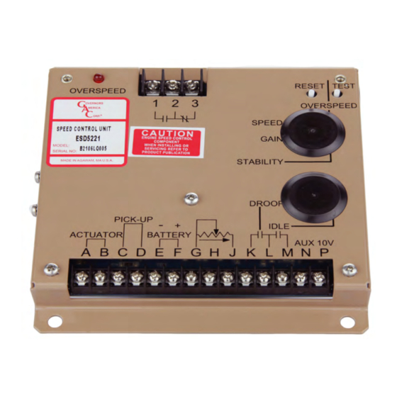
WIRINg
TermInaL
DefInITIon
A & B
ACTuATOR (+/-)
PICK-uP *
C & D
(D is ground)
E & F
BATTERy (-/+)
G
GROuND
H & G
Droop Range
J
Variable Speed Input
K & L
DROOP Select
M
Idle Select
N
Accessory Input
P
Accessory Power Supply
use #16 [1.3 mm
] or larger wire. Long cables require an increased wire size to minimize
2
voltage drops.
•
Wires must be twisted and/or shielded for their entire length
•
Gap between speed sensor and gear teeth should not be smaller than 0.02 in. [.5mm]
•
Speed sensor voltage should be at least 1 V AC RMS during crank
•
#16 [1.3 mm
] or larger wire
2
•
A 15 amp fuse must be installed in the positive battery lead to protect against reverse
voltage
•
Battery positive (+) input is Terminal F must be fused for 15 amps as shown in the Wir-
ing diagram in this section to protect against reverse voltage.
Add jumper to decrease droop range
0 - 5 V DC
Droop active when closed
Close for Idle
Load Sharing / Synchronizing,
Supplies +10 V regulated supply to accessories. No more than 20 mA of current can be
drawn from this supply. Ground reference is Terminal G. A short circuit in this terminal can
damage the speed control unit.
2
in
Dimensions
[mm]
noTeS
ESD5550-5570 Series Speed Control Unit 1-2021-E1 PIB1003
Governors America Corp. © 2021 Copyright All Rights Reserved
Vertical orientation allows fluids
to drain in moist environments.
Avoid extreme heat
Mount in a cabinet, engine
enclosure, or sealed metal box.