GAC ESD5200 Series 매뉴얼 - 페이지 3
{카테고리_이름} GAC ESD5200 Series에 대한 매뉴얼을 온라인으로 검색하거나 PDF를 다운로드하세요. GAC ESD5200 Series 7 페이지. Speed control unit
4
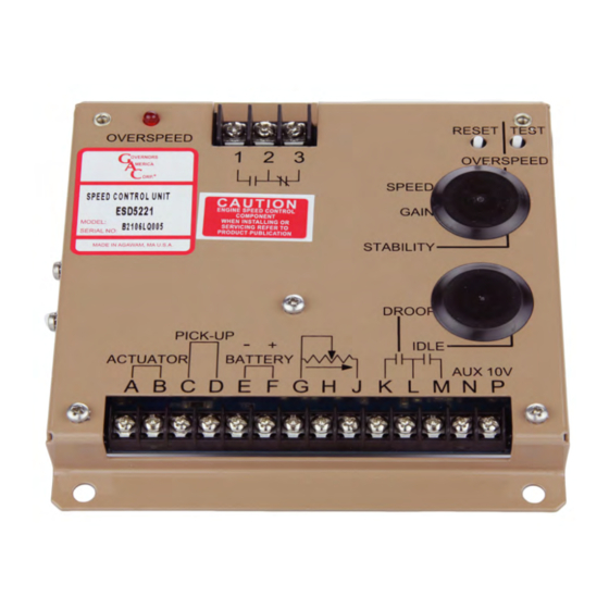
WIRINg - CONTINUED
TermInaL
DefInITIon
A & B
Actuator (+/-)
Magnetic Speed Pickup
C & D
(D is ground)
E & F
Battery Power (-/+)
G
Ground Signal
H & G
J
Variable Speed Input
K & L
Droop Select
M & L
Idle Select
N
Accessory Input
P
Accessory Power Supply
An overspeed shutdown device, independent of the governor system, must be provided to prevent loss of engine control
which may cause personal injury or equipment damage. Do not rely exclusively on the governor system to prevent over-
speed. A secondary shutoff device such as a fuel solenoid must be used.
When wiring the ESD5200 series controller:
1.
Use shielded cable for all external connections to the ESD5221 control unit.
2.
One end of each shield, including the speed sensor shield, should be grounded to a single point on the ESD case.
3.
Terminal A, B, E,and F should be #16 or larger. Long cables require increased wire size to minimize voltage drops.
4.
Battery positive (+) Terminal F should be fused for 15 A.
5.
Magnetic speed sensors Terminals C and D must be twisted and or shielded for the entire length.
6.
The gap between the speed sensor and the ring gear teeth should be smaller than 0.20 in [0.45 mm] usually obtained by backing out
3/4 turn after touching ring gear teeth. Speed sensor voltage should be at lease 1 V AC RMS during cranking.
7.
If auto synchronization is used alone, not with a load sharing module, use a 3 Ω resistor between Terminal N and P to match the
voltage between the speed control unit and the synchronizer.
8.
When operating at the upper end of the control unit frequency range, add a jumper wire between Terminal G and J to increase the
frequency range of the control unit over 7000 Hz.
9.
Do not over-tighten terminals. Torque to no greater than 9.0 in-lb ±2.5 [1.01 ±0.28 N∙m].
aDDInG a PoTenTIomeTer
Use a single remote speed adjustment potentiometer to adjust engine speed. Select the
desired speed range and the corresponding potentiometer value.
If the exact range is not found select the next higher range potentiometer. Connect the
potentiometer as shown in the wiring diagram.
5
ADJUSTMENTS BEFORE ENgINE STARTUP
Make sure the following adjustments are set before starting the engine.
SeTTInG
GAIN
STABILITY
SPEED TRIM CONTROL
Use 16 AWG [1.3 mm
2
•
Wires must be twisted and/or shielded for their entire length
•
Gap between speed sensor and gear teeth should not be smaller than 0.02 in. [.5mm]
•
Speed sensor voltage should be at least 1 V AC RMS during crank
•
16 AWG [1.3 mm
2
•
Install a 15 A fuse in the positive battery lead to protect against reverse voltage
•
Battery positive (+) input is Terminal F
Add Jumper for Droop Increase
0 - 5 V DC
Active When Closed
Load Sharing / Synchronizing,
Supplies +10 V regulated supply to accessories. No more than 20 mA of current can be drawn from this
supply. Ground reference is Terminal G. A short circuit in this terminal can damage the speed control unit.
PoSITIon
Middle Position
Middle Position
Middle Position
noTeS
] or larger wire
] or larger wire
GAIN
3
ESD5200 Series Speed Control Unit 1-2021-C3 PIB1030
Governors America Corp. © 2021 Copyright All Rights Reserved
SPEED
OVERSPEED
ON
1
2
STABILITY