GAC 176 Series 매뉴얼 - 페이지 3
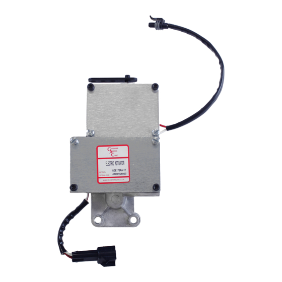
{카테고리_이름} GAC 176 Series에 대한 매뉴얼을 온라인으로 검색하거나 PDF를 다운로드하세요. GAC 176 Series 4 페이지. Integral electrical actuator
5
PREPARATION
If the Bosch "A" size fuel injection pump with left hand rack (as viewed from rear)
is equipped with a mechanical governor, it must be removed. GAC recommends
that this modification be performed by a qualified fuel injection service facility.
The following procedure lists the general steps required to remove the mechan-
ical governor.
NOTE
The mechanical governor will release oil during removal.
1.
Remove the rear housing from the mechanical governor and disconnect
the governor linkage from the fuel rack. Remove the flyweight assembly
with special tools, Bosch part number KDEP-2998 and KDEP-2918, can
be obtained from an authorized Bosch service center, with KDEP-1068
tappet holding tools that will be needed during reassembly.
2.
Remove the intermediate governor housing which leaves only the rack
and camshaft protruding from the pump. Remove the camshaft bearing
from the governor cover and press it into the bearing plate provided with
KT176A, which must be ordered separately. The plate must have coun-
tersunk holes to accommodate recessing the mounting screws.
3.
Install tappet holding tools. Bosch part number KDEP-1068, to remove
the tappet spring load from the camshaft.
4.
Install the bearing and cover assembly with its gasket onto the pump
using the four original governor cover screws to temporarily retain the
bearing plate and release the tappets of all cylinders.
5.
Measure the camshaft end-play by moving the shaft axially from one
mechanical stop to the other. Total travel should be 0.05mm to 0.2mm
(0.002" to 0.008"), adjust the shim pack behind the camshaft bearing as
required to meet specification.
6
INSTALLING THE ACTUATOR
All hardware needed to attach the actuator to the pump is located in kit KT291
(See page 2), which is supplied with the actuator. The following instructions will
refer to the included figures on the next page.
1.
The mounting surface of the pump must be clean. Attach the rack link (1)
to the left hand side of the fuel rack with an M5 x 10mm screw (2) (that
includes a patch of adhesive) (Fig.1). Tighten the screw to 3 – 4 N•m so
that the link is aligned axially on the rack.
2.
Remove the lower screws of the bearing retainer plate and replace them
with the mounting retainers (3) (Fig.1, 2 & 3). Attach the mounting retain-
ers with the shorter end thread into the pump and torque to 9 N•m.
3.
Insert adjusting sleeve screws (13) (Fig.2) into threaded lower mounting
holes on the actuator. Temporarily place the actuator over the rack and
mounting retainers and onto the pump face. Check that the actuator is flat
and it contacts both the pump face and the shoulders of the mounting re-
tainers. If necessary, adjust the screws (13) (Fig.2). The upper and lower
mounting points of the actuator must be equally supported. Remove the
actuator from the pump.
4.
Remove both of the actuator covers. DO NOT remove the lever (16)
(Fig.1) from the actuator shaft. Place the O-ring seal into the groove (4)
(Fig.3) on the mounting face of the actuator. Apply a small amount of
grease to the O-ring to hold it in place.
5.
Swing the armature out of the actuator so that the lever (16) (Fig.1) is out
of the way. Guide the actuator over the rack and onto the lower mounting
retaining studs (3) (Fig.1, 2 & 3). Attach the top of the actuator to the
pump with the M8 x 16mm socket head screw (5) (torque to 29 N•m),
lock washer (6) and flat washer (7) (Fig.1). Use M6 hex nuts (8) and
flat washers (9) to secure the lower position of the actuator (Fig.2 & 3).
Torque the nuts to 9 N•m.
6.
Pull on the rack so that it is as far out of the pump as possible. Check
that it moves freely. Place the return spring (10) over the rack. Place the
spring retainer (11), the shut-off plate (12), and the M10 locking nut (24)
over the threads on the rack link (1) (Fig.1). The flats on the shut-off plate
(12) must engage the flats on the link (1). Tighten the nut to 6 – 8 N•m
and insure that the shut-off plate is vertical and secure.
7.
Test the engagement of the shut-off mechanism with the rack linkage.
Swing the lever back into the actuator. Push on the armature to ensure
that the rack linkage operates smoothly and returns immediately when
released. Reattach the lower actuator cover (23) and tighten the screws
(20 & 22) (Fig.3) to 2 – 3 N•m.
8.
Loosen the mounting screw (17) and the fastener screw (18) so that the
lever (16) can be adjusted in its slot (Fig.1). Adjust the lever so that the
bearing pushes the rack 0.5 - 0.7 mm away from its stop position. Hold
the lever in this position and tighten the screws (18) and (17) (Fig.1) to
7 N•m. The rack is now adjusted. Confirm that the operating lever screw
(19) (Fig.1) is tightened to 13 N•m. Inspect the assembly to make sure
all screws are tight.
9.
The lever has a maximum fuel adjustment set screw (14) (Fig.1). This
screw is used to restrict the fuel rack from 1 to 14.5 mm. With the fuel
pump operating on the engine, the maximum fuel setting can be set
to provide specific horsepower. For the final maximum fuel setting, it
is recommended that a thread locking fluid, such as Loctite 243, be
applied to the threads of the fuel setting screw. Hold the screw in the
required position with the appropriate hex-key and tighten the lock-nut
(15) (Fig.1) to 8.0 – 8.8 N•m.
10.
Move the manual shut-off lever to the stop position and insure that the
fuel is completely shutoff and the engine stops.
11.
With the engine shut down, install the upper chamber cover (21) with
the four screws (20 & 22) and flat washers (25) (Fig.3). Note that when
installed, the internal lever (16) or its stop screw (14) (Fig.1) must not hit
the cover. Tighten the screws to 2 – 3 N•m. Check for any oil leaks. Lock
wire the screws (22) (Fig.3) for tamper resistance.
Setting high fuel levels may cause the maximum fuel adjusting
CAUTION
screw to hit the top cover, which can change the minimum fuel
position. This could lead to a dangerous condition. When setting fuel levels
above 17mm, insure that the adjusting screw does not contact the top cover
at minimum level. Make sure that the cold start magnet is de-energized when
adjusting the actuator with the cold start option.
7
WIRING
The 176 Series Integral Electric Actuator is prewired for 12 or 24VDC operation.
Use the included cable harness or make up a cable harness to connect the
actuator to the speed control unit.
Do not use the 176 Series actuator on a 32-volt system. Contact
WARNING
the factory for assistance.
The engine should be equipped with an independent shut down
CAUTION
device to prevent overspeed, which can cause equipment dam-
age or personal injury.
Minimum of 16 AWG wire should be used for the connection be-
NOTE
tween actuator and speed control. The position feedback sensor
can use 18 AWG if desired.
176 Series Electric Actuator 10.15
3
PIB 2053 C
© 2015 Copyright All Rights Reserved