GAC EEG6550 Series 매뉴얼 - 페이지 9
{카테고리_이름} GAC EEG6550 Series에 대한 매뉴얼을 온라인으로 검색하거나 PDF를 다운로드하세요. GAC EEG6550 Series 13 페이지. Enhanced electronic governor
9
ADJUSTING FOR STABILITY
Once the engine is running at operating speed and at no load, the following governor performance adjustments can be made to
increase engine stability.
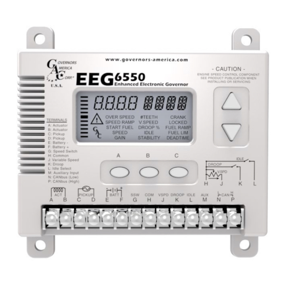
GaIn - raTeD SPeeD & IDle SPeeD
The EEG6500 is equipped with two separate gains, one for rated speed, the other for idle speed. Both are set using the GAIN setting
on the Quikset Menu.
GaIn TYPe
1.
Selected when IDLE input is disconnected.
RATED SPEED
1.
Connect the idle input to ground.
IDLE SPEED
2.
Change GAIN value.
3.
Disconnect Idle input from ground to switch back to rated. Idle icon will blink.
ParameTer
1.
Increase this parameter until instability develops.
2.
Then, gradually decrease this parameter until stability returns.
A.
GAIN
3.
Finally, decrease this parameter one increment further to ensure stable performance.
If instability persists, adjust the next parameter.
4.
1.
Follow the same adjustment procedure as the GAIN parameter.
B.
STABILITY
2.
If instability persists, adjust the next parameter.
C.
DEADTIME
1.
If fast instability occurs, switch DEADTIME to low and repeat steps A & B.
noTe
Normally adjustments made at no load achieve satisfactory performance. For further performance see Section 14, System Troubleshooting.
10
ADJUSTING FOR DROOP
After the initial set up is completed and the # of Teeth, Crank Termination Speed and Rated Speed are set, position the external switch
connecting Terminals H and K on to activate the DROOP mode following these sequence steps.
1.
Go to the Advanced menu: Press and hold all three buttons simultaneously for two seconds to switch to Advanced Menu.
2.
Confirm that the VSPD (Variable Speed / Fixed Speed Control) is OFF. Default position is off.
3.
Confirm that the LEAD circuit is OFF. Default position is on.
4.
Set the NLCU (No Load Current) to the measured / displayed current value when operating at no load rated speed (default
value is 0.5 amps.) The NLCU entered must be less than the flcU and the difference between the two must be at least 0.5 A.
If an invalid combination is entered a warning will be flagged and the parameters will be default to 0.5 A and 4.0 A.
5.
Set the FLCU (Full Load Current) to the measured / displayed current value when operating at full load rated speed (default
value is 4.0 amps.)
6.
Return to the Main Menu: Press and hold all three buttons simultaneously for two seconds to switch to the Main Menu.
7.
Select and set DROOP to the desired percentage.
8.
Change the Speed parameter, which turns into the DROOP OFFSET.
9.
This sets the RPM, above operating speed, to which the system will be commanded when DROOP is enabled. This is an offset
value.
eXamPle
1500 RPM operating speed x 0.05 (5.0% droop) = 75 RPM Input 75 RPM, this is the offset value.
11
VARIABLE SPEED GAIN
When in variable speed operation, the PID will use the VGLO (Varaible Gain Low) and VGHI (Variable Gain High) in place of the
GAIN parameter on the main screen. These variable speed Gain values are used to interpolate between the low and high points in
parallel with speed to provide gain ramping as speed is adjusted.
If the GAIN on the main menu is changed while in variable speed mode, the unit will flash LOCK to indicate the parameter
noTe
is not available in that mode.
aDjUSTmenT ProceDUre
QUIKSeT menU
aDjUSTmenT ProceDUre
EEG6550 Enhanced Electronic Governor 5-2020-A1
9
Governors America Corp. © 2020 Copyright All Rights Reserved
PIB1118