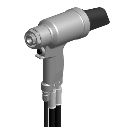
Gage Bilt GB2600 원본 사용 설명서 - 페이지 12
{카테고리_이름} Gage Bilt GB2600에 대한 원본 사용 설명서을 온라인으로 검색하거나 PDF를 다운로드하세요. Gage Bilt GB2600 16 페이지. Installation tool

WARNING:
Only qualified and trained personnel should perform overhaul.
WARNING:
Personnel must read and understand all warnings and cautions.
WARNING:
Tool must be maintained in a safe working condition at all times and examined on a daily basis for damage or
wear. Any repair should be done by qualified personnel trained on Gage Bilt procedures.
WARNING:
Disconnect tool from its power source before performing overhaul. Severe personal injury may occur if power
source is not disconnected.
WARNING:
Excessive contact with hydraulic oil and lubricants should be avoided (See SDS documents for all applicable
materials
WARNING:
When operating, repairing or overhauling tool, wear approved eye protection. Do not look in front of tool or
rear of tool when installing fastener.
WARNING:
Use only Gage Bilt hydraulic hoses and couplings, or equivalent, rated for 10,000 psi. (689.5 bar) working pressure.
WARNING:
Ensure air hose is securely connected to avoid possible hose whipping (Air Actuated Tools only).
WARNING:
Do not exceed the maximum relief-valve setting stated on the tool and manual.
WARNING:
Relief valve must be installed with four flats towards the rear of the cylinder.
Note:
Dispose of hydraulic oil in accordance with manufacture safety datasheet.
All tool materials are recyclable except rubber o'rings, seals and wipers.
If a tool is performing poorly or leaking, a complete overhaul may be necessary. Service Kit (GB2600KS) contains a complete set of
o'rings, back-up rings and screws.
Perform overhaul in a clean, well lit area using care not to scratch or nick any smooth surface that comes in contact with an o'ring.
Use of Lubriplate® #630-AA (Gage Bilt part no. 402723) or equivalent during reassembly to prevent tearing or distorting of o'rings.
1. Disconnect control cord assy (585034) / air line (750154) from power supply.
2. Disconnect hydraulic hose (206020) from power supply.
3. Remove hydraulic coupler-male (585047) & hydraulic coupler-female (585038) from hydraulic hose (206020) and drain into a
container.
4. Push rearward on the piston until the remaining hydraulic oil is drained into an approved container. Discard oil in accordance
with all local practices.
5. Complete this step only if the switch, connector or wire is to be repaired. Remove the retaining nut and locking ferrule from the
strain relief (263021). Loosen the set screw (401731) and remove the electric actuator (240122). Loosen and remove the two
wires from the electric actuator (240122). Remove the control cord assy (585034) from the tool.
6. Remove the deflector (262032) from the barbed retainer (260015), by simultaneously twisting and pulling.
7. Remove the socket head cap screw (405189) from the barbed retainer (260015), then insert two 5/16" (7.9 mm) pins in opposite
holes in the rear of the barbed retainer (260015) and unscrew from the handle assy (260020).
8. Slide the front gland assembly (260014) off of the piston assy (260011) and remove the front polyseal (406064), wiper housing (260007),
back-up ring (401125), oring (400831) and polyseal (406158).
9. Remove all O'rings, Back-up rings, Wipers, Polyseals and Glyd Rings. Clean parts in mineral spirits or other o'ring compatible
solvent being sure to clean o'ring grooves. Inspect components for scoring, excessive wear or damage.
10. Reassembly sequence is opposite of disassembly. Be sure relative positions of o'rings, polyseals and back-up rings are as
shown in exploded view and part list.
Coat hose fitting threads with a non-hardening teflon® thread compound such as Slic-tite®. DO NOT USE TEFLON® TAPE.
(See hydraulic thread preparation pg.10).
Apply hot glue to wire connections of the electric actuator (240122) to ensure wires DO NOT contact each other or handle assy.
(Electric actuated installation tool GB2600 only).
1.
When tool life is met, drain hydraulic oil from tool and dispose of the hydraulic oil in accordance with SDS datasheet.
2.
Disassemble tool and remove all rubber o'rings, seals, wipers and hydraulic hoses. All tool materials are recyclable except rubber
o'rings, seals, wipers and hydraulic hoses. Dispose of rubber materials in accordance with all environmental regulations applicable
in your area.
GB2600 / GB2600A INTALLATION TOOL S/N: 1001 AND ABOVE
PLEASE CONTACT GAGE BILT FOR ALL OTHER SERIAL NUMBERS
).
Note: The four flats on the 260019 relief valve must face towards the rear of the tool. (See pg. 11).
TOOL DISPOSAL
OVERHAUL
12
REV 1/20
