Hi-Force AHP187 사용 설명서 - 페이지 8
{카테고리_이름} Hi-Force AHP187에 대한 사용 설명서을 온라인으로 검색하거나 PDF를 다운로드하세요. Hi-Force AHP187 9 페이지. Air driven hydrotest pumps
INSTRUCTION MANUAL – AIR DRIVEN HYDROTEST PUMPS:
Model Series: AHP10.AHP26, AHP36, AHP58, AHP107, AHP187, AHP275, AHP425,
AHP2-036, AHP2-060, AHP2-097, AHP2-144, AHP2-237, AHP3-040, AHP3-060, AHP3-100, ATDP63 ATDP125,
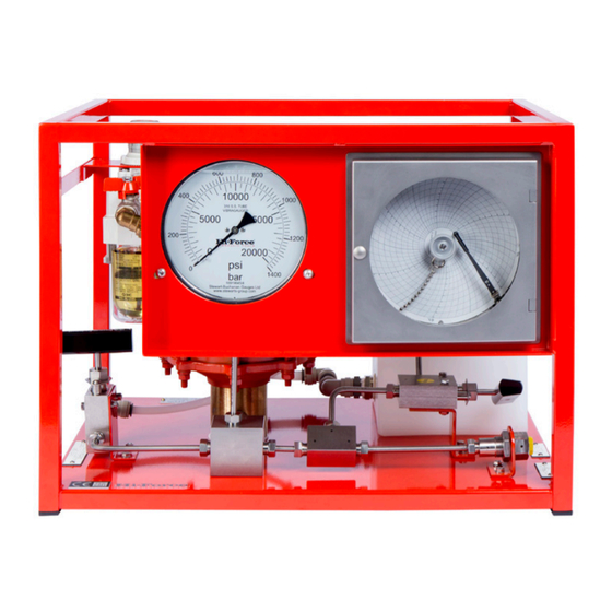
Slowly adjust the pump air pressure-regulating
valve clockwise, the pump will reciprocate and
start to displace fluid into the system and build
up pressure, the pressure generated can be
viewed on the hydraulic pressure gauge.
The maximum pressure achievable at various
air pressures can be seen on the ATDP
brochure page under the heading "Max-
output pressure at airline input pressure" e.g.
ATDP63 if 80 psi air pressure is applied then the
maximum pressure the pump can generate is
approximately 80psi x the pump ratio 63/1 =
5,040psi (347bar). ATDP125 if 80 psi air pressure is
applied then the maximum pressure the pump
can generate is approximately 80psi x the
pump ratio 125/1 = 10,000psi (700bar). ATDP216
if 80 psi air pressure is applied then the
maximum pressure the pump can generate is
approximately 80psi x the pump ratio 216/1 =
17280psi (1191bar).
If a slower pump cycle rate is required the drive
air pressure can be reduced by turning the air
pressure regulating valve anticlockwise and/or
by partially closing the pump air on /off valve
The pump can operate as a transfer pump filling
the vessel under test with liquid.
The pump will gradually and naturally start to
cycle at a slower rate as the pressure in the
vessel under test increases until it stops (stalls)
when a balance of forces is reached i.e. when
the air drive pressure x air drive piston area = stall
pressure x driven hydraulic piston area.
The pump will hold pressure indefinitely unless a
leak occurs, at which time the pump will
automatically cut in once the leak rate reaches
a certain level to try to maintain the pressure in
the system.
If the air supply is turned to the OFF position the
hydraulic pressure generated will hold on the
pumps integral check valves (in small volume
systems the hydraulic pressure may fall slightly
and then stop whilst the check valve balls
reseat, this is normal).
The pump will continuously stroke if the circuit is
open (flushing mode).
Close the air start/stop valve to stop the pump
at any point, if required.
Once the test is completed to release hydraulic
system pressure:
Turn the air on/off valve to the off position
Hi-Force Limited – Prospect Way – Daventry – Northants NN11 8PL – United Kingdom
Tel: +44(0) 1327 301000: Fax: +44(0) 1327 706555: Website: www.hi-force.com
ATDP216,
Turn
the
air
anticlockwise until it fully is wound out
Slowly open the pressure release valve and fluid
will return via the drain hose to drain until zero
pressure is indicated on the pump hydraulic
pressure gauge.
It is possible to pre-set the pump so it stalls
automatically at the desired pressure. This can
be done by plugging the pressure outlet port
and operating the pump. Adjust the air pressure
regulator gradually upwards such that the
pump stalls at the correct pressure. Release the
pressure by opening the pressure release valve.
Close the pressure release valve once more to
check the set pressure. Provided that no
adjustments are made the pump will repeat this
set pressure when connected to a pressure
vessel.
FAULT FINDING
ALL
NORMAL
PRECAUTIONS
PERFORMING MAINTENANCE ON HYDRAULIC
AND PNEUMATIC EQUIPMENT.
1.
PUMP NOT RUNNING PROPERLY OR
ERRATICALLY OR STOPS OPERATING
(a) Pump mufflers beginning to block
with ice or iced up.
(b) Pump fluid supply starved causing
cavitations or irregular pumping
action
(c) Pump air changeover valve sticking
or pump external air pilot switches
not engaging properly
(d) Insufficient lubrication
(e) Air supply starved
(f) Dirty air supply
.
2.
LOSS OF HYDRAULIC PRESSURE
(a) Insufficient fluid supply
(b) Hydraulic check valves in pump
leaking
(c) Hydraulic fluid leaking past seals in
pump (Fluid can be seen leaking
from the vent hole under one or
each hydraulic cylinder).
(d) Leak from pipe- work
(e) Hydraulic pressure release valve
leaking back to drain or left partially
open accidentally
pressure-
regulating
RECOMMENDED
SAFETY
SHOULD
BE
TAKEN
valve
WHEN