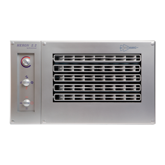
Aircommand HERON 2.2 설치 지침 매뉴얼 - 페이지 2
{카테고리_이름} Aircommand HERON 2.2에 대한 설치 지침 매뉴얼을 온라인으로 검색하거나 PDF를 다운로드하세요. Aircommand HERON 2.2 10 페이지.
Aircommand HERON 2.2에 대해서도 마찬가지입니다: 소유자 매뉴얼 (17 페이지)

INSTALLING THE CONDENSER SET
I
Marking out the floor
Use the floor template as provided (or refer to fig. 3). Both, or either end of the con/set may be hard against
a wall or panel, but the back of the unit must have sufficient clearance to allow easy access to the line
valves (see fig. 4). Once a convenient position has been decided upon, place the template, side marked
"Inside Wall", hard against the inside skin of the van, and mark out the six 114 mm diameter (4
condenser air inlet holes, and the square compressor well hole (see fig. 3).
Note: Check to see if any structural floor members will interfere with any of these holes. It is essential that
the compressor well is unimpeded.
The air inlet holes will tolerate some obstruction.
However the total area must not be less than
75% of the inlet holes in the chassis.
We recommend that a hole saw be used to cut
out the six round holes. If a structural member is
beneath, then the complete cut out can be
removed. The gap between the top of the
structural member and the underside of the unit
(i.e. the floor thickness) will help in overcoming
the restriction of the member.
I
Marking out the wall
Now mark out the hole in the wall for the
condenser discharge grille (see fig. 5).
Mark out the position and size of the air outlet
hole, from inside the van, using the floor as
reference.
Pilot holes can be drilled at the four corners, and
the hole cut out from the outside. It is essential
to frame up this hole to give a firm seal to the air
outlet from the con/set and to stop any discharge
air from entering the wall space.
I
Positioning of the Con/set
Lay down a generous bead of silicone on the
floor to match the perimeter of the Con/set. Now,
lift the Con/set into position, and check that the
compressor well does not interfere and prevent
the con/set from sitting firmly on the floor.
Push the Con/set hard up against the wall.
It is vital that the Con/set seals hard against
the inside wall to ensure no hot air leakage
during operation.
To secure the Con/set in position, use the two
hold down clips provided (see fig. 4). These clip
over the edge of the chassis. At least one clip
should be installed on the back edge to ensure the
good airseal is maintained against the inside
wall.
Screw the clips firmly to the floor.
Normally install condenser
set opposite to annexe
Line Valves
Drill pilot holes at each corner
15
Hatched area
is the cut out
Outline of the
condenser set
FLOOR
CONDENSER AIR OUTLET HOLE VIEWED FROM INSIDE THE VAN
2
1
/
")
2
50
178
10
Comp.
180
well
107
237
372
Figure 3
Clips
Figure 4
430
Figure 5
265
390
135
95
