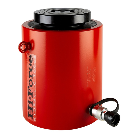
Hi-Force HHA Series 사용 설명서 - 페이지 3
{카테고리_이름} Hi-Force HHA Series에 대한 사용 설명서을 온라인으로 검색하거나 PDF를 다운로드하세요. Hi-Force HHA Series 4 페이지. Hydraulic cylinders

Model Series: HVL, HPS, HLS, HSS, HAS, HHA, HHS, HHR, HDA, HFL, HFG, HSG, HGG, HPC.
of the cylinder several times until the operation is
smooth.
Double Acting Cylinders: Position the cylinder
below the level of the hydraulic pump. On its side
with the couplings facing upwards (as in B. in the
diagram above). Fully extend and retract the piston
several times until the operation is smooth.
Note: When long hoses are used (especially in the
case of smaller capacity cylinders) the above
procedure may not completely remove all the air
from the system. In these cases contact your Hi-
Force representative for advice on pre-filling hoses
with hydraulic oil.
Note: Fitting adaptors to cylinders. The collar
threads are designed to facilitate the full capacity of
the cylinder when the adaptors are fully engaged
over the full collar thread length.
Warning:
Some
require that the cylinder be used at no more
than 50% of its rated capacity. Refer to the
accessory instructions for additional information.
5.0 Operation.
A hydraulic is required to operate the cylinder
ranges covered by this instruction. Please refer to
relevant Hi-Force hydraulic pump operation
instructions for full details of the chosen pumps
relevant instructions.
Single Acting cylinders have different methods of
return of the piston, these are either spring assisted
return or load assisted return.
Double Acting cylinders have the piston powered in
both directions by means of the hydraulic pump
used.
The cylinder stop ring where fitted is
designed to withstand the full load of the
cylinder. However it is advisable to reduce wear and
extend the service life of the cylinder that the
operator uses less than the full stroke and load
wherever possible.
On models of cylinder where a stop ring is
fitted it is imperative that the piston is not
over extended. On these models, Hi-Force, employs
a red marker band on the piston which will become
visible when the maximum stroke length of the
piston has been achieved. Any attempt to extend
the piston beyond this point will cause hydraulic oil
Hi-Force Limited – Prospect Way – Daventry – Northants NN11 8PL – United Kingdom
Tel: +44(0) 1327 301000: Fax: +44(0) 1327 706555: Website: www.hi-force.com
INSTRUCTION MANUAL – HYDRAULIC CYLINDERS:
cylinder
attachments
to by-pass via the overflow hole in the cylinder. This
action when performed with the cylinder under
pressure can damage the seals. Should this action
have taken place the cylinder must be returned to
your local Hi-Force authorized service centre for the
seals to be replaced.
Base Mounting holes (where provided) are
not suitable for withstanding the full
retraction force of double acting cylinders. These
mounting holes are for location purposes only.
When lowering loads on both single and
double acting cylinders, the load may
descend faster than expected. The use of a manual
check valve (HFV66) is recommended for precise
load lowering control.
Tilting saddles are fitted as standard to
certain models of Hi-Force cylinders and are
available as an operational accessory on other
models. These saddles accommodate up to 5
misalignment of load, and will reduce (but not
eliminate) the risk of cylinder damage due to lateral
loading.
Always ensure that the piston of the cylinder
contacts the load to be lifted as squarely as
possible – this also applies when tilting saddles are
used.
HFL and HFG – Failsafe cylinders
Hi-Force HFL and HFG Models are fitted as standard
with a failsafe locking ring. The purpose of this
feature is should the application requires that the
cylinder becomes the load holding device, the
locking collar can be screwed down the piston until
it comes in contact with the cylinder barrel.
Applying the lock ring in this manner provides a
mechanical support to the load that is being lifted.
With the lock ring fully engaged, the hydraulic
pressure can be released from the system and the
cylinder becomes a solid mechanical support.
Always ensure that the lock ring is in full
contact with the cylinder barrel before
releasing the system pressure.
HPC Pull Cylinders:
All Pull cylinders must be operated with the
full Clevis/Eyelet attachments engagement
utilized.
o
of
