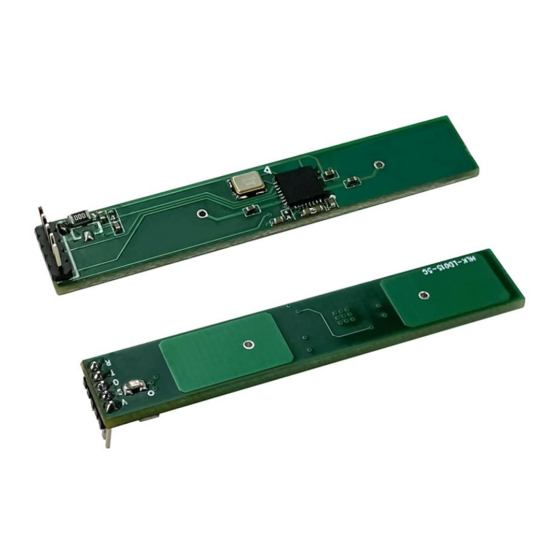
Hi-Link HLK-LD015-5G 사용자 설명서 - 페이지 7
{카테고리_이름} Hi-Link HLK-LD015-5G에 대한 사용자 설명서을 온라인으로 검색하거나 PDF를 다운로드하세요. Hi-Link HLK-LD015-5G 8 페이지. Radar module

vcc
OUT
1 S
9. Schematic diagram of detection range
The sensing sensitivity of the radar sensor can be configured through the MCU, and its limit
sensing distance is 10 meters, and the actual sensing distance can be adjusted appropriately as
required. The following is a schematic diagram of the radar detection range under the condition of
hanging height. If the sensitivity is set higher, the detection range will increase accordingly. The
dark area in the figure is the high sensitivity area, which can be fully detected in the area, and the
light color area is the low sensitivity detection area, objects can be basically detected in this area.
Figure 6. Schematic diagram of HLK-LD015-5G detection range (unit: m)
Precautions
When installing, avoid metal shells or parts on the front of the antenna to avoid shielding the
signal. Plastic or glass is allowed, but the obstruction should not be close to the front of the
HLK-LD015-5G
1 S
Figure 5. Module power-on sequence diagram
Inductive OUT=1
No induction OUT=0
,
Page 5 / 6
User Manual
