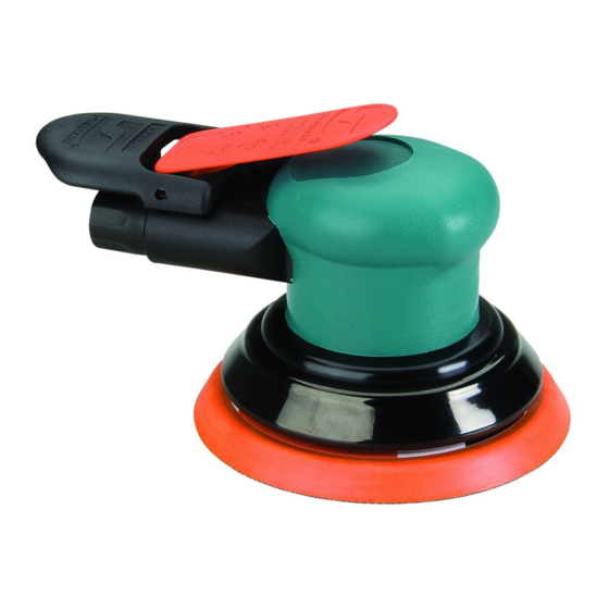
Dynabrade Dynorbital-Spirit 59018 안전, 운영 및 유지보수 - 페이지 7
{카테고리_이름} Dynabrade Dynorbital-Spirit 59018에 대한 안전, 운영 및 유지보수을 온라인으로 검색하거나 PDF를 다운로드하세요. Dynabrade Dynorbital-Spirit 59018 13 페이지. 12,000 rpm random orbital sander
Dynabrade Dynorbital-Spirit 59018에 대해서도 마찬가지입니다: 안전, 운영 및 유지보수 (4 페이지), 안전, 운영 및 유지보수 (8 페이지)

Motor Assembly/Disassembly Instructions - Dynorbital -Spirit
Important: Manufacturers warranty is void if tool is disassembled before warranty expires.
A Full Service Repair Kit P/N 57098, is available which includes special repair tools for correct disassembly/assembly of the sander.
To Disassemble
1. Disconnect sander from air supply.
2. Invert the sander, and place the 57092 Repair Collar (supplied in the 57098 Full Service Repair Kit) around the housing and secure in a vise. Padding
can be used on the vise jaws to protect the housing. Important: Do not over tighten the sander in the vise. If the sander is held too tight the
removal of the lock ring and air motor will be difficult.
3. Remove sanding pad with the 50679 26 mm Open-end Wrench (supplied with the sander).
4. Insert 56058 Lock Ring Tool (supplied in 57098 Full Service Repair Kit) into the corresponding tabs of lock ring. Loosen the 59058 Lock Ring
turning it counterclockwise.
5. Remove the 59058 Lock Ring and the 50659 O-Ring from the air motor assembly (3/32" and 3/16" dia. orbits only).
6. Remove 01024 O-Ring and 98463 Retaining Ring from motor assembly.
7. Fasten a 2 in. bearing separator (P/N 96346 available) around the 59051 Cylinder just below the upper 59055 Bearing Plate. Place the air motor
assembly in a #2 arbor press (P/N 96232 available) so that the separator is resting on the table of the arbor press and with the balancer pointing down.
8. Use a flat nose 3/16" dia. drive punch as a press tool. Place it against the small end of the motor shaft balancer and push the shaft out of the
upper 58368 Bearing.
9. Remove the rotor, vanes and rotor key from the motor shaft balancer.
10. Again fasten the 2 in. bearing separator between remaining 59055 Bearing Plate/58368 Bearing and the top of the balancer. Rest the separator on the
table of the arbor press and push the motor shaft out of the 58368 Bearing.
11. Disassemble the balancer assembly as follows:
a.) Place motor shaft assembly into a soft jaw vise. Using a thin screwdriver, pick out the end of 95630 Snap Ring and peel out. This will loosen the
balancer assembly.
b.) Screw the threaded portion of the 56056 Bearing Puller (supplied in 57098 Repair Kit) into the 59059 Balancer Shaft and heat the outside of the
motor shaft balancer to approximately 200° F (approximately 10 seconds with a propane torch). Now, using the slider weight, pull
the assembly out.
c.) Press off 56052 Bearing with a bearing separator and remove bearing seal and bearing shield.
12. If during step 11, the 56052 Bearing remains in the motor shaft balancer, it can be removed by the heating the shaft balancer again and using either an
inside bearing puller or a blind hole bearing puller.
To Assemble:
Important: Be certain parts are clean and in good repair before assembling.
1. Assemble the balancer assembly as follows:
a.) Install 95630 Snap Ring onto balancer shaft. Install 95628 Shield with convex face toward hex of balancer shaft.
b.) Install 56053 Seal. Note: Be certain seal is pressed completely over shaft step.
c.) Apply 1 drop of #271 Loctite
of the 59059 Balancer Shaft.
d.) Press fit 56052 Bearing with seal side toward hex of balancer shaft up to shaft step as shown in Drawing 1. This must be a firm press fit for
proper retention of bearing.
2. Place the motor shaft balancer in a soft jaw vise with large end-up.
3. Apply 1 drop of #609 Loctite
assembly into the motor shaft balancer until 56052 Bearing are firmly seated at bottom. Squeeze 95630 Snap Ring into groove in motor shaft balancer
to complete the assembly. Remove from vise. Place 50659 O-Ring and 59058 Lock Ring onto the motor shaft balancer (3/8" orbit models only).
4. Apply 1 drop of #609 Loctite
5. Install 58368 Bearing onto the motor shaft balancer down to the shoulder as shown in Drawing 2.
6. Press 59055 End Plate onto 58368 Bearing as shown in Drawing 3 and check for smooth rotation.
7. Install the 98451 Rotor Key and 57090 Rotor on the motor shaft balancer. Place the 56073 Vanes into the rotor slots.
Note: Vanes should be lubricated with Dynabrade Air Lube P/N 95842 (or equivalent) before installation.
8. Place 59051 Cylinder Assembly over rotor. The "short" line-up post goes toward the front bearing plate.
9. Place 58368 Bearing into 59055 Bearing Plate. Apply 1 drop of #609 Loctite
Drawing 1
Balancer Shaft Assembly
®
(or equivalent) and spread over several places around inside diameter of 56052 Bearing and the outside diameter
®
(or equivalent) and spread over several places around the outside diameter of the 56052 Bearing and slide balancer
®
(or equivalent) and spread around lower area of motor balancer shaft where the front 58568 Bearing will be located.
(Continued on next page.)
57091
Bearing Press Tool
56052 Bearing
Shaft Step
Bearing Seal and
Bearing Shield
®
(or equivalent) and spread around inside diameter of 58368 Bearing.
Drawing 2
7
57091
Bearing Press Tool
58368 Bearing
Motor Shaft Balancer
Balancer Shaft Assembly
™
