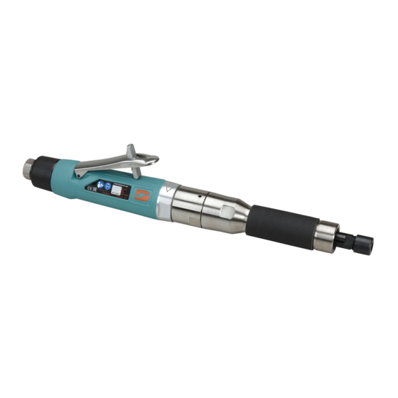
Dynabrade 52680 안전, 운영 및 유지보수 매뉴얼 - 페이지 5
{카테고리_이름} Dynabrade 52680에 대한 안전, 운영 및 유지보수 매뉴얼을 온라인으로 검색하거나 PDF를 다운로드하세요. Dynabrade 52680 8 페이지. 1hp die grinder

Disassembly Instructions - 1 Hp Straight-Line Planetary Geared Die Grinders
Important: Manufacturer's warranty is void if tool is disassembled before warranty expires.
Disconnect tool from power source before tool repair.
Motor Disassembly:
(The special repair tools referred to in the instructions can be obtained from dynabrade.)
1. Remove the collet assembly from the tool.
2. Fit the 51989 Repair Collar to the wrench flats on the aluminum part of the motor housing and secure the tool
in a vise.
3. Remove the gear casing/planetary cover from the housing. (Right Hand Threads)
4. Remove the 04014 Set Screw(s) and the planetary gear assembly(ies) from the gear casing/planetary cover.
5. Fasten the 96346 Bearing Separator between the 53191 Ring Gear and the rear 02552 Bearing. Place the
separator on the 96232 Arbor Press so that the threaded male spindle is pointing down. Use the largest
diameter end of the 96214 Bearing removal tool to push against the planetary carrier and press the planetary
carrier from the bearing.
6. Secure the 53165 Planetary Carrier in a soft aluminum or bronze jaw vise and remove the 04032 Spindle Nut.
7. Press the planetary carrier from the front 02552 Bearing.
Note: The following instructions only apply to the double planetary models.
Remove the 02552 Bearing and the 53673 Carrier from the 53694 Planetary Cover. Press the carrier from the
bearing by using the 96232 Arbor Press. Press the 53678 Shafts from the 53673 Carrier and remove the
53193 Gears. Remove the ring gear from the motor housing.
8. Remove the 96498 Wave Spring and the 53620 Adapter along with the 95438 O-Ring.
9. Pull the motor out of the housing.
10. Carefully hold the rotor stationary and remove the governor assembly with a flat blade screw driver.
(Left Hand Thread)
11. Fasten the 96209 Motor Repair Clamp around the 51925 Cylinder. Position the motor repair clamp on the table
of the arbor press so that the rotor pinion gear is pointing down. Use a 1/8" dia. drive punch as a press tool and
push the rotor out of the 02057 Bearing.
12. Remove the 02057 Bearing from the 51923 Rear Bearing Plate.
13. Press the rotor out of the 54520 Bearing. Also remove the 51922 Front Bearing Plate and the 51927 Spacer
from the rotor.
14. Remove the 54520 bearing and shims from the front bearing plate.
Silencer Disassembly/Assembly:
Note: Refer to the exploded view of the tool on page 4 to identify the correct silencer assembly and parts.
Follow the view to determine the correct sequence of assembly, adhesive required, and torque specification.
Motor Disassembly Complete.
Assembly Instructions - 1 Hp Straight-Line Planetary Geared Die Grinders
Motor Assembly:
Important: Clean and inspect parts before assembling.
(The special repair tools referred to in the instructions can be obtained from Dynabrade.)
1. Install the 51927 Spacer onto rotor.
2. Place a .004" thickness of shims into the 51922 Front Bearing Plate and install the 54520 Bearing into
the bearing plate.
3. Use the 96232 Arbor Press and the 96244 Bearing Press Tool to install the front bearing/plate assembly onto
the front of the rotor. (The bearing press tool should push against the inner race of the bearing when it is
being installed onto the rotor.)
4. The clarence between the rotor and the front bearing plate can be checked with a .001" feeler gauge. The
clarence should be between .001" -.0015". If a change in the adjustment is required repeat steps 2-4 removing
or adding shims as required.
5. Once the proper rotor gap clarence is achieved, install the 51926 Blades (4) that have been lubricated with
95842 Dynabrade Air Lube.
6. Install the 51925 Cylinder over the rotor so that it will seat with the raised bearing plate boss. Also, align the pin
with the notch in the cylinder.
7. Peel the backing off the 51924 Gasket. Align and adhere it to the 51923 Rear Bearing Plate.
8. Place the 51923 Rear Bearing Plate over the bearing journal of the rotor so that the raised boss on the bearing
plate will seat with the cylinder. Align the pin with the notch in the cylinder. Be sure that the air inlet opening in
the rear bearing plate aligns with the air inlet opening in the cylinder. If these do not align, then the cylinder
must be flipped end to end. (Repeat steps 6-8.)
(continued on next page)
