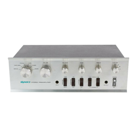
DYNACO PAT-4 조립 설명서 - 페이지 2
{카테고리_이름} DYNACO PAT-4에 대한 조립 설명서을 온라인으로 검색하거나 PDF를 다운로드하세요. DYNACO PAT-4 20 페이지. Power supply
DYNACO PAT-4에 대해서도 마찬가지입니다: 조립 설명서 (16 페이지)

Table of Contents
Table of Contents ................................................................................................................ 2
Table of Figures .................................................................................................................. 2
Section 1: About This Manual ............................................................................................ 3
Who Should Attempt these Projects? ............................................................................. 3
Tools You'll Need........................................................................................................... 3
Project Overview ............................................................................................................ 4
Line Amp Distortion Reducer ..................................................................................... 4
Tone Control Switch ................................................................................................... 4
Important Safety Notes ................................................................................................... 4
Section 2: Line Amp Distortion Reducer............................................................................ 5
Line Amp Characteristics ........................................................................................... 5
How the Distortion Reduction Works......................................................................... 5
The Modification in a Nutshell ................................................................................... 5
Preparing to Remove the Circuit Boards .................................................................... 5
Modifying the Left Channel Circuit board ................................................................. 6
Modifying the Right Channel Circuit board ............................................................... 9
Inspection and Reassembly ......................................................................................... 9
Section 3: Tone Control Switch ........................................................................................ 10
Before You Begin ......................................................................................................... 10
Pre-wiring the Tone Control Switch ............................................................................. 10
Optional Gain Reducing Resistors ................................................................................ 13
Disassembling the PAT-4 Preamp ................................................................................ 13
Removing the HI FILTER switch. ............................................................................ 14
Mounting the tone control switch ............................................................................. 14
Wiring in the tone control switch.............................................................................. 14
Installing the Treble No-Click Resistors ................................................................... 16
Reassemble the PAT-4 .............................................................................................. 16
Using the Tone Control Switch..................................................................................... 17
Pops and Clicks ......................................................................................................... 17
Gain Trim Resistors ...................................................................................................... 18
Schematic .................................................................................................................. 19
Appendix: The Toothpick Trick ................................................................................... 20
Table of Figures
Figure 1-applying thermal compound and installing the heat sink ..................................... 7
Figure 2-New transistor with heatsink installed on PCB .................................................... 8
Figure 3-MPSW45A Pinout ................................................................................................ 8
poles (center terminals) and throws (outer terminals). These gray lines are not on the
actual switch. The gain resistors are optional, and not included with the kit ................... 12
Figure 6-Installing the treble no-click resistors on eyelets 16, 17, and 18 ....................... 16
control switch .................................................................................................................... 19
Page 2 of 20
