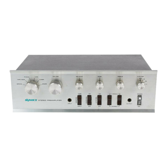
DYNACO PAT-4 조립 설명서 - 페이지 11
{카테고리_이름} DYNACO PAT-4에 대한 조립 설명서을 온라인으로 검색하거나 PDF를 다운로드하세요. DYNACO PAT-4 16 페이지. Power supply
DYNACO PAT-4에 대해서도 마찬가지입니다: 조립 설명서 (20 페이지)

Remove the Old Power Supply
1. Disconnect the PAT-4 from your music system.
2. Unplug the power cord and allow the preamp to sit for one minute before moving
on.
Caution: Be sure that the preamp power is unplugged! 120 VAC can be lethal! 240 VAC
3. Remove the 4 screws that hold the cover in place, 2 on the left side and 2 on the
right side.
4. Lift the cover straight up and set it aside in a safe place.
5. Get masking tape and a pen ready. You will be labeling the wires that you are
about to remove.
6. Refer to Figure 3. Desolder (or cut close to C29) the following wires from C29,
the tall 3-section capacitor. As you de-solder each wire, place a masking tape
label on the wire to aid re-assembly (if directed to do so).
a. 2 red wires connected to the semi-circle section of the capacitor. Label
these two wires "P17P5".
b. 2 red wires connected to the square section of the capacitor. Label these
two wires 38V.
c. 1 red wire connected to the triangle section of the capacitor that comes
from the terminal strip holding diodes D1 and D2. Remove the other end
of this wire that connects to the terminal strip.
d. 2 black wires, one long, and one short, connected to one of the ground
terminals of C29.
e. 2 black wires, one long and one short, connected to the other of the ground
terminals of C29.
f. the transformer center-tap wire (typically has a red-yellow herringbone
pattern) that is connected to the third ground terminal of C29. Label this
wire CT.
7. Remove the two screws, nuts, and lock washers that hold C29's clamp into the
chassis. Lift out C29.
8. Cut the other two low-voltage transformer (red) wires close to terminal strip
where they attach to D1 and D2. Label these wires X1 and X2. It doesn't matter
which wire receives which label. D1, D2, and the terminal strip are unused after
the revised power supply is installed.
can be lethal!
Page 11 of 16
