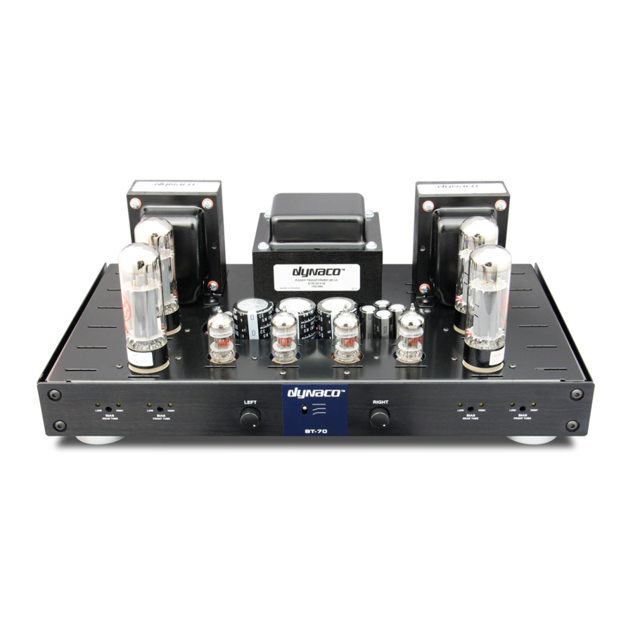
DYNACO ST-70 조립 설명서 - 페이지 5
{카테고리_이름} DYNACO ST-70에 대한 조립 설명서을 온라인으로 검색하거나 PDF를 다운로드하세요. DYNACO ST-70 14 페이지. Driver 6gh8 ecf82 for the ab-q-st70 auto bias module
DYNACO ST-70에 대해서도 마찬가지입니다: 설치 및 사용자 설명서 (9 페이지)

19. Connect one end of a 5 ½ inch wire from lug 8 of V1 (S). Connect the other end of this wire to the
quad cap filter capacitor 40 Mfd lug having the SQUARE symbol (S)
20. Connect one end of a short 2 inch jumper wire from the 80 mfd lug on the quad cap filter capacitor
having the HALF-CIRCLE symbol (S). Connect the other end of this jumper wire to the 20 Mfd filter
capacitor terminal furthest to the RIGHT. NOTE – this filter capacitor lug has NO SYMBOL.
21. Connect one end of a 2200 ohm (2.2 K ohm – in with the VTA parts) from the 20 Mfd lug with NO
SYMBOL (S). Connect the other end of this resistor to the remaining 30 Mfd lug on the quad cap
filter capacitor with a TRIANGLE symbol that faces the front of the amp.
22. Connect one end of a 5 inch wire to the quad cap filter capacitor 30 Mfd lug with the TRIANGLE
symbol and have the other free end face the PCB cut out (S). The other free end of this wire will be
connected at a later step.
23. Connect one end of a short 2 or 3 inch wire from any of the quad cap TWIST TABS that have a
hole in them (S). Connect the other end of this wire to one of the grounding lugs next to the quad
cap.
24. Connect one end of a 5 inch wire to one of the grounding lugs next to the quad cap and have the
FREE END of this wire face the PCB cutout. Solder all 6 connections on the two grounding lugs.
(S) When you solder the connections on these two grounding lugs count to make sure that you
have SIX wires connected to these two lugs. You should have the following wires connected here.
It doesn't matter which wire is connected to which grounding lug.
A. The RED-YELLOW wire from the power transformer
B. A wire from the LEFT BLACK speaker terminal
C. A wire from the RIGHT BLACK speaker terminal
D. A wire coming from lug #2 of the seven lug terminal strip
E. A wire connected to one of the grounding twist tabs of the quad cap
F. A 5 inch wire with one end free (The other end of this 5 inch wire will be connected in a later
step). It is important that these two grounding tabs be soldered properly as this is the main
grounding point for the entire amp.
25. Connect one end of a 1000 ohm 1 watt resistor to pin #5 of V3 (S). Connect the other end to pin #6
of V3. Keep the leads to this resistor and the next three resistors in this step at 3/8 of an inch or
less. Connect one end of a 1000 ohm 1 watt resistor to pin #5 of V2 (S). Connect the other end to
pin #6 of V2. Connect one end of a 1000 ohm 1 watt resistor to pin #5 of V6 (S). Connect the other
end to pin #6 of V6. Connect one end of a 1000 ohm 1 watt resistor to pin #5 of V7 (S). Connect the
other end to pin #6 of V7.
26. Obtain the last two tube sockets that will be installed in the two power take off holes in the front of
the chassis. DO NOT INSTALL THEM AT THIS TIME. Hold the socket with the back facing you and
the keyway pointing to the LEFT. Connect a 6 inch wire to pin #8 (S) of one of the sockets and run
the wire to the LEFT of the socket as viewed from the BACK of the socket. Connect a 9 inch wire
to pin #4 (S) of this socket and run this wire to the LEFT also. Place this socket with the two wires
attached aside. This will be installed in the LEFT power takeoff socket later.
27. Repeat step 29 for the other remaining tube socket (the keyway again faces to the LEFT as viewed
from the back) except run the wires to the RIGHT. This socket will become the RIGHT power take
off socket. Neither of these two sockets will be used for any "power take off" but two pins on each
tube socket will be used to measure bias on the four output tubes.
