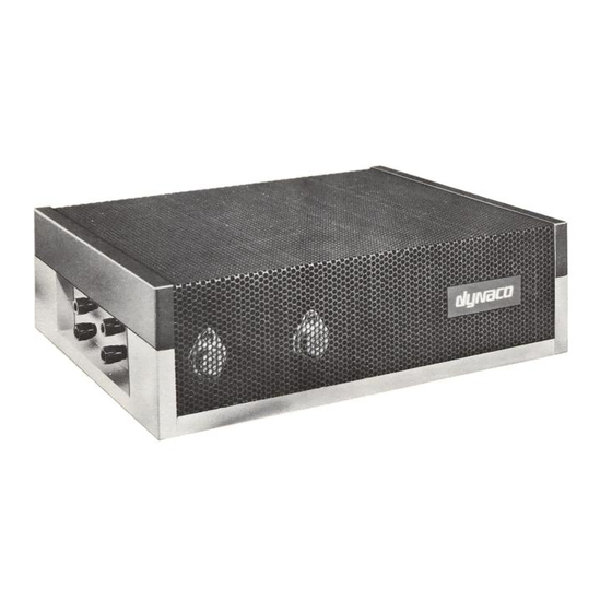
DYNACO Stereo 120 매뉴얼 - 페이지 2
{카테고리_이름} DYNACO Stereo 120에 대한 매뉴얼을 온라인으로 검색하거나 PDF를 다운로드하세요. DYNACO Stereo 120 10 페이지. Installing the really big heatsink for the power supply

Table of Contents
Table of Contents ................................................................................................................ 2
Table of Figures .................................................................................................................. 2
Section 1: About this Manual ............................................................................................. 3
Who Should Attempt this Project? ................................................................................. 3
Tools You'll Need........................................................................................................... 3
Project Overview ............................................................................................................ 3
Important Safety Notes ................................................................................................... 4
About Components ......................................................................................................... 4
Recommended Solder ..................................................................................................... 4
Section 2: Removing the PSUG Power Supply and stock Heatsink ................................... 4
Opening the Amplifier .................................................................................................... 4
Remove the PSUG power supply and heatsink .............................................................. 5
Separate the PSUG and the Heatsink .............................................................................. 5
Replace 3 components to increase the power delivered ............................................. 6
Add a mounting hole to the bottom of the chassis ...................................................... 7
Mount the power supply to the Really Big Heat Sink ................................................ 7
Mount the PSUG/Really Big Heat Sink Assembly to the Chassis ............................. 9
Inspect for clearance ................................................................................................... 9
Testing the Result ....................................................................................................... 9
Reassemble the amplifier ............................................................................................ 9
Resistor Color Code ...................................................................................................... 10
Table of Figures
Figure 1-Location of the four screws that hold the cover to the base ................................. 5
Figure 2-Remove the two screws that hold the heatsink to the chassis .............................. 5
Figure 3-Install the male-female standoffs ......................................................................... 6
Figure 4-Showing locations of C3, R3, and R11 ................................................................ 7
Figure 5-layout for added mounting hole ........................................................................... 8
Figure 6-screw sizes to mount PSUG, remember to tighten the screws ............................. 8
Figure 7-use 6-32x3/8" screws to mount the heatsink ........................................................ 9
Figure 8-demonstrating the resistor color code ................................................................ 10
Page 2 of 10
