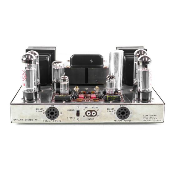
DYNACO Stereo 70 복원 매뉴얼 - 페이지 7
{카테고리_이름} DYNACO Stereo 70에 대한 복원 매뉴얼을 온라인으로 검색하거나 PDF를 다운로드하세요. DYNACO Stereo 70 20 페이지. Series ii tube amplifier
DYNACO Stereo 70에 대해서도 마찬가지입니다: 복원 매뉴얼 (5 페이지), 소유자 매뉴얼 (12 페이지), 조립 지침 (16 페이지)

Page 7
11) De-solder the power transformer lead (Red / Yellow) connected to system ground
lug located immediately to the left of the Quad capacitor. You may cut any
remaining wires connected to these lugs and then remove and discard.
12) Next, examine the dual RCA input connector. If it is cracked or worn or you plan
to replace it, you may cut the wires to all four posts and discard. Alternatively if it
is clean and re-useable, carefully de-solder and clean each post and store.
13) Immediately to the left of the input connector you will find the stereo-mono
switch. De-solder and clean its lugs and store for reuse.
14) The two 8 pin octal sockets located on the front of the amplifier will be retained
however we will only be using them for bias adjustment purposes. Therefore you
may cut all of the wires except pin 8. De-solder and clean pin 8 on both sockets.
Remove both and store for reuse.
15) Locate the 7 pin terminal strip immediately to the left of the power transformer
(below the left output transformer). De-solder completely terminals 5, 6, & 7 (See
Figure 1). These terminals mount a 3 leaded ceramic (small flat circular) capacitor
and two power transformer leads (Green/Yellow and Brown/Yellow). Carefully
remove the ceramic capacitor and clean the solder on its leads. You may cut the
remaining wires and components connected to pins 1 through 4 connected to this
terminal strip.
16) Locate Left Output tube socket associated with V2 (left side nearest the center).
De-solder the wires connected to pins 2, 3, 4 & 7. This will free all of the power
and output transformer leads for the left channel. Using your ohmmeter, measure
the resistance of the 15.6 ohm bias set resistor connected from V2/pins 1&8 and
ground. If it is not open carefully de-solder it, clean its leads and store for reuse.
17) Repeat step 16 at V7 on the right channel.
18) De-solder the power transformer Red/ Black Stripe lead connected to the
selenium rectifier. Cut the remaining wire connected to the other selenium
rectifier terminal and remove and discard the selenium rectifier.
19) De-solder all of the wires connected to the rectifier socket (V1). The socket will
be replaced but the four power transformer wires (2X yellow and 2X red) will be
reused. Remove and discard the tube rectifier socket.
20) Next, you may remove the three transformers. Begin with the power transformer
and next remove the two output transformers. The power transformer is held in
place with 8-32 nuts on posts originating from the transformer. There are also
wire hold-down clamps. Be sure you keep all of this hardware.
21) Once you remove the three transformers, you should now have access to the
hardware securing the choke and seven lug terminal strip. Remove and store the
choke. Remove and discard the 7 pin terminal strip.
22) The remainder of the parts mounted on the chassis may be now removed. Since
the will not be retained they may be discarded. You may want to keep all of the
mounting hardware for spares. If you will be retaining the original Dynaco driver
pc board (not recommended) you can de-solder the wires connected to the 23
terminals associated with this board.
Dynaco Stereo 70 Power Amplifier
Restoration Manual
Detailed Procedure & Guide
R0 4-03
7
