CEL-MAR ADA-4010A 사용자 설명서 - 페이지 7
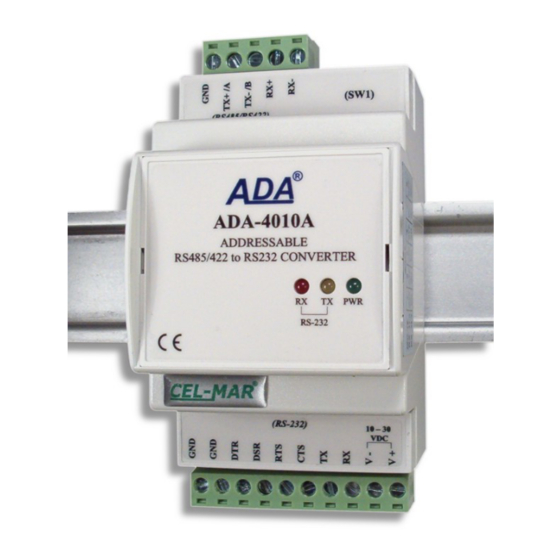
{카테고리_이름} CEL-MAR ADA-4010A에 대한 사용자 설명서을 온라인으로 검색하거나 PDF를 다운로드하세요. CEL-MAR ADA-4010A 16 페이지. Rs-485/rs-422 to rs-232 addressable converter
CEL-MAR ADA-4010A에 대해서도 마찬가지입니다: 사용자 설명서 (13 페이지)

ADA-4010A
3.3.2. RS485(2W) BUS CONNECTION
PC or
MASTER device
RS232
RS232
connector
connector DB-
DB-9M/DTE
9F/DCE
(2) Rx
Tx (2)
(3) Tx
Rx (3)
(5) GND
GND (5)
Fig 6. Example connection of ADA-4010A to RS485(2W) 2-wire bus and galvanic separation SLAVE device
3.3.3. GND TERMINAL CONNECTION
Connection of GND terminals of RS485/422 interfaces, devices connected to RS485/422 bus, should be done in the case of a
potential difference of the signals grounds on interfaces RS485 / RS422, which prevents proper data transmission.
Cannot connect to the GND terminal - cables screens, PE circuit of electrical installation, signals grounds of other devices.
3.3.4. LINE TERMINATION Rt
The application of Line Termination (terminator) Rt = 120 ohms will reduce electrical reflection in data line at high baud rate. It is not
needed below 9600Bd. Should be used the Line Termination resistor if the distance is over 1000m @ 9600Bd or 700m @ 19200Bd,
and if the disturbance in transmission will appear.
Example connection of resistor Rt are shown on fig.5 & fig.6. Two resistors Rt=120 W , 5%, 0,25W is delivered with ADA-4010A.
3.3.5. CONNECTION OF RS232 INTERFACE DEVICES
Connections of SLAVE device with RS232 interface to ADA-4040A are shown on fig.5 & fig.6.
3.4. POWER SUPPLY CONNECTION
To connect power supply to the converter, should have DC power supplies (regulated) output voltage from 10 V= to 30V=, min.
nominal power 2W, e.g. DR-15-24. Power cable from DC power supplies to device can not be longer than 3m. Should connect positive
(+) end of DC power supplies to V+ device terminal and negative (-) end to V- on terminal block. ADA-4010A has protection against
power supply reverse connection. If after power connection the green LED PWR on front panel is not lit, check correctness of power
supply connection (polarisation).
4. ACTIVATION
The converter can be power on after properly connection according to section above.
If after connection power supply on front panel will not light green led PWR, check correctness of power supply connecting
(polarization). When data is present the LEDs Tx and Rx should blink
ADA-I1040
Screw
connector
RS485 / RS422
Tx+/ A
Rt
Tx-/ B
Rx+
Rx-
GND
RS232
RS485(4W) bus
9600Bd/8/O/1
RS232
SLAVE
9600Bd/8/E/1
7
RS232
SLAVE
SLAVE
2400Bd/8/N/2
19200/Bd/7/N/2
