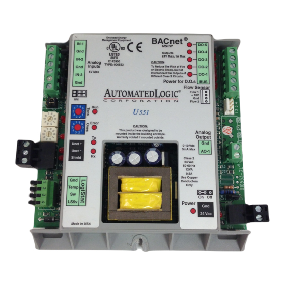
Automated Logic U551 기술 지침 - 페이지 8
{카테고리_이름} Automated Logic U551에 대한 기술 지침을 온라인으로 검색하거나 PDF를 다운로드하세요. Automated Logic U551 11 페이지.

U module
LogiStat
4
LS5v
Sw
3
Temp
2
Gnd
1
Figure 7. Connecting the LogiStat to the U551
Strip 1/4 inch off the ends of the wires before
connecting.
1. Insert wire
into opening
Figure 8. Flip Lever Wiring
Refer to the section "Writing GFBs for the
U551" on page 9 for more information about
using a LogiStat sensor.
Digital Output Wiring
The U551 has five digital outputs that can be
connected to a maximum of 24 Volts AC/DC
(see Figure 9). Each output is a dry contact
(rated at 1A maximum) that is configured as
normally open.
DO-2
DO-1
BUSS
Figure 9. Digital Output Wiring
Be sure the module's power is off before
connecting any inputs or outputs.
Revised 8/14/02 • U551
LogiStat
1 2 3 4
2. Press black
tab down to
connect wire
DO
DO
Gnd
24VAC
+
To verify each output's operation, lock the
output to a known condition using the
Function Block's Properties page in WebCTRL
or the Parameter page in SuperVision, then
make sure the equipment operates as
specified.
Analog Output Wiring
The U551 has one analog output that
supports voltage devices from 0 to 10VDC
(see Figure 10). The device being controlled
must have a minimum of 2000 Ohms
resistance measured from its input to ground
and must share the same ground as the
module.
Gnd
AO-1
Figure 10. Analog Output Wiring
Be sure the U551's power is off before wiring
any inputs or outputs. Connect the output
wiring to the screw terminals on the module.
To verify each output's operation, lock the
output to a known condition on the Function
Block's Properties page in WebCTRL or the
Parameter page in SuperVision, then make
sure the equipment operates as specified.
Using Flow Sensors
The U551 controls air flow in the zone using:
• a USF (single) or UDF (dual) air flow
sensor and an actuator connected to
two digital outputs
In a dual duct system, you can use the
module's built-in actuator for one duct and
the UASF for the other. You must indicate
which of these methods you are using for
flow control on the UNI module driver's
Properties page in WebCTRL or on the
8
© 2002 Automated Logic Corporation
-
0 to 10V
+
