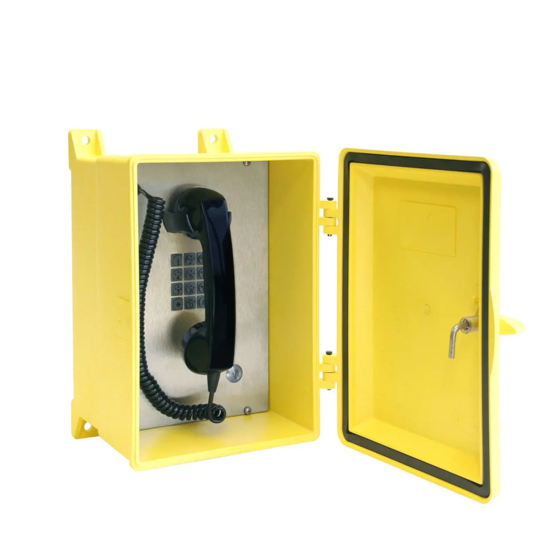
GAI-Tronics 354-700RD 매뉴얼 - 페이지 9
{카테고리_이름} GAI-Tronics 354-700RD에 대한 매뉴얼을 온라인으로 검색하거나 PDF를 다운로드하세요. GAI-Tronics 354-700RD 17 페이지. 354-70x series nema 4x voip telephone

NEMA 4X VoIP Telephones
Cable Use
Size
LAN
Power
Inputs
Output contacts
Status Indication
Power
The power LED located on the VoIP PCBA illuminates when power is applied to the telephone. Refer to
Figure 7 for the location.
Heartbeat
The heartbeat LED located on the VoIP PCBA will flash when the telephone is operational over the
WLAN. Refer to Figure 7 for the location.
: It may take up to a minute for the heartbeat to initialize after power up.
N
OTE
EACT
The EACT LED located on the VoIP PCBA will turn ON when VoIP PCBA is connected to an Ethernet
device and will flash when data is being transmitted. Refer to Figure 7 for the location.
P:\Standard IOMs - Current Release\42004 Instr. Manuals\42004-520A.docx
03/17
Figure 6. Internal PCBA Connections
Table 4. Recommended Cabling
Cat5 or Cat5e UTP cable with an RJ-45 connector
Two-conductor, No. 18 AWG is typical
Two-conductor, No. 22 AWG is typical
Two-conductor, No. 18 AWG is typical
Pub. 42004-520A
Page 9 of 15
