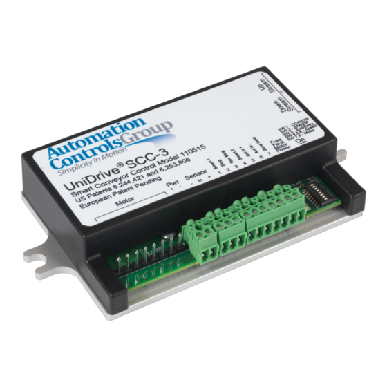
Automation Controls Group UniDrive SCC-3 설치 및 문제 해결 매뉴얼 - 페이지 7
{카테고리_이름} Automation Controls Group UniDrive SCC-3에 대한 설치 및 문제 해결 매뉴얼을 온라인으로 검색하거나 PDF를 다운로드하세요. Automation Controls Group UniDrive SCC-3 11 페이지. Smart conveyor control generation iii

Mount the Control
3.1
Mount the control in a location where the motor cable
reaches the connection header without putting strain on the
cable connector or the header.
Select a Motor
3.2
Select the motor you will be using. Properly match the
control settings to the motor in use to deliver the best and
most predictable performance.
SW8:
SW7:
Motor:
OFF
OFF
100W24
OFF
ON
125W24
Table 5: Motor Selection Switch Settings
Select a Speed
3.3
Three switches determine the operating speed, making it
simple to match speeds in multiple zones. The actual speed
selected also depends on the motor that you selected in the
previous step, so set those switches first.
There is also an option to use a 0-10 V differential input for
remote, dynamic speed adjustment while the system is
running.
Switches:
SW6
SW5
SW4
OFF
OFF
OFF
OFF
OFF
ON
OFF
ON
OFF
OFF
ON
ON
ON
OFF
OFF
ON
OFF
ON
ON
ON
OFF
ON
ON
ON
Table 6: Operating Speeds
Configure the Location
3.4
Identify the location of the control and then set Switch 3.
If this control is placed at the entry end of the conveyor
section where objects are loaded, set Switch 3 to the ON
position.
If this control is placed between two other SCC-3
controls, set Switch 3 to either ON or OFF.
If this control is placed at the exit end of the conveyor
section where objects are discharged, set Switch 3 to the
OFF position.
Entry:
In Between:
ON
ON or OFF
Table 7: Switch 3 Settings for Control Location
Comments:
Previously STD
Previously HO.
Speed Selection (RPM):
100W24
125W24
280
350
248
310
216
270
184
230
152
190
120
150
88
110
56
70
Exit:
OFF
Configure the Operating Mode
3.5
Identify the operating mode that this section of conveyor will
use for transporting objects and then set Switch 2.
If the conveyor will be operating in the most
conservative, conventional Zero-Pressure Accumulation
(ZPA) mode, set Switch 2 to the OFF position.
If the conveyor will be operating in the higher
throughput, enhanced accumulation ZIP mode, set
Switch 2 to the ON position.
If the conveyor will be operating in the Slug or Slug
Reverse mode, or as a stand-alone unit, Switch 2 may be
set to the ON or OFF position because the Slug and Slug
Reverse inputs override all of the accumulation logic.
Slug, Slug Reverse,
ZPA:
or Stand-alone:
OFF
OFF or ON
Table 8: Switch 2 Settings for Operating Mode
Configure the Rotation
3.6
Identify the proper direction of rotation for the motor shaft
in order to move objects from the upstream (entry) end of
the conveyor towards the downstream (exit) end of the
conveyor. The direction of rotation is defined when viewed
from the back side of the motor with the shaft extending
away from the viewer.
For clockwise rotation
For counter-clockwise rotation
Configure Communications
3.7
Make the peer-to-peer communication connections. These
controls pass request and permission signals between adjacent
zones over 6-wire modular phone cables. See Section 5.3 for
information on the cable orientation.
At the exit end of the conveyor, do not connect the
phone cable to the Downstream Peer-to-Peer NPN RJ-25
Connection (item 8).
Connect one end of a 6-wire phone cable to the
Upstream Peer-to-Peer NPN RJ-25 Connection (item 7)
and then connect the other end of the phone cable to
the downstream phone jack on the adjacent upstream
control.
At each adjacent intermediate control, connect another
6-wire phone cable to the Upstream Peer-to-Peer NPN
RJ-25 Connection (item 7) and then connect the other
end of that cable to the downstream phone jack on the
adjacent upstream control.
At the entry end of the conveyor, do not connect a
phone cable to the Upstream Peer-to-Peer NPN RJ-25
Connection (item 7).
SCC-3 Product 110515 Revision 1.3 April 19, 2018 | Page 7
ZIP:
ON
set Switch 1 to the ON position.
set Switch 1 to OFF.
