Dynamic DX2-PMA90LG 설치 매뉴얼 부록 - 페이지 9
{카테고리_이름} Dynamic DX2-PMA90LG에 대한 설치 매뉴얼 부록을 온라인으로 검색하거나 PDF를 다운로드하세요. Dynamic DX2-PMA90LG 20 페이지. The ultimate powerchair control solution

3 Installation
3.1 Connect to the DX System
In contrast to all other DX2-PMA variants, the DX2-PMA90LG module only has one
DX BUS socket. The socket that the other variants use as a second DX BUS connection
is used for the DX2-GYRO module.
To connect multiple DX Modules to the Power Module, either use a DX BUS Y-cable
(GCB65231) or a straight cable to a 4-way DX BUS socket (DX-SKT-X4).
3.2 Connect to the DX2-GYRO module
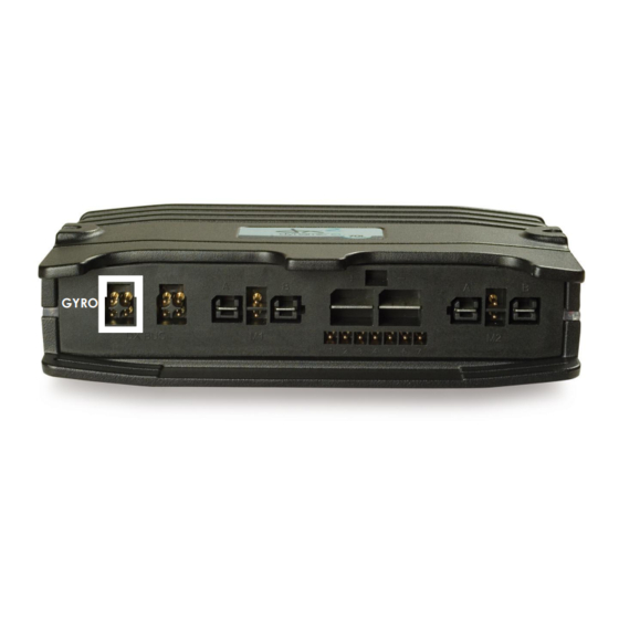
The leftmost socket on the DX2-PMA90LG connects to the DX2-GYRO module.
To avoid confusion with the DX BUS socket, the GYRO socket is clearly marked with a
white rectangle. The DX2-GYRO module has a cable with a white connector that can
help to recognise the correct connection: the white connector goes into the socket
with the white rectangle.
: Issue 2.03 - May 2012
GBK65148
DX BUS
Precautions:
Connect high current modules such as an Actuator Module as close as
possible to the Power Module (see DSM section 3.2).
GYRO
Precaution:
The DX2-GYRO connector is physically identical to the DX BUS connector.
If both cables are swapped, no damage will occur to either the Gyro
module or the power module. However, the DX System will not start up if the
connectors are swapped. It is therefore important to make sure that the
connectors are inserted in the correct socket.
9
